



 English





Choosing between injection molding and thermoforming affects more than the initial tooling quote. A large equipment cover may look straightforward in CAD, yet develop thin corners during forming. An injection-molded housing may have a low unit price, but require costly mold changes when mounting features or assembly interfaces are revised.
Injection molding is generally better suited to parts with integrated features, controlled interfaces, and repeat production that can justify the mold investment. Thermoforming is worth considering for large, thin-walled parts with shell-like geometry, particularly when lower initial tooling costs matter. A large cover with a few simple openings may suit thermoforming, while a housing with multiple mounting bosses and snap fits is more likely to favor injection molding.
| Comparison | Thermoforming | Injection molding |
|---|---|---|
| Starting material | Thermoplastic sheet or film | Plastic pellets or resin |
| Forming method | Heated sheet formed over or into a mold | Molten plastic injected into a closed mold |
| Typical parts | Large covers, panels, trays, liners, and enclosures | Housings, connectors, clips, brackets, and detailed components |
| Tooling investment | Generally lower for comparable applications | Generally higher due to core-and-cavity tooling |
| Wall thickness | Varies with material stretching and draw depth | Defined by cavity geometry; affected by filling and cooling |
| Integrated features | Some features require secondary machining or hardware | Ribs, bosses, and snap fits can often be molded in |
| Secondary operations | Trimming and machining are commonly required | Often limited to gate removal, finishing, or assembly |
| Production economics | Suitable for many large custom parts; thin-gauge packaging also runs at high volumes | Attractive when tooling investment can be spread across repeat production |
A lower tooling quote can be misleading if the formed part needs extensive trimming, machining, or assembly. The sections below examine how geometry, tooling requirements, and production costs affect the choice.
How Do Thermoforming and Injection Molding Work?
Thermoforming and injection molding both shape thermoplastics, but they start with different material forms. Thermoforming heats a plastic sheet until it becomes pliable, then forms it against a mold. Injection molding melts resin pellets and fills a closed mold under pressure. These differences affect the geometry each process can produce and the work required after forming.
The Thermoforming Process
Thermoforming starts with a plastic sheet or film. The sheet is clamped and heated until it reaches a formable state. Vacuum, compressed air, or mechanical force then draws it against a mold surface. After cooling, the part is released and trimmed to its final outline.
A typical thermoforming sequence includes:
- Sheet loading and clamping: A thermoplastic sheet is secured in a forming frame.
- Heating: Heating elements bring the sheet to its forming temperature. Uneven heating can lead to inconsistent material distribution.
- Forming: Vacuum, pressure, a plug assist, or a combination of methods pushes the softened sheet against the mold.
- Cooling and release: The formed sheet cools until it can hold its shape and be removed from the tool.
- Trimming and finishing: Excess material is cut away. Openings, mounting features, and edges may need CNC routing, drilling, or other secondary operations.
Common thermoforming methods include:
- Vacuum forming: Uses vacuum pressure to pull the heated sheet against the tool.
- Pressure forming: Adds compressed air to improve surface detail and feature definition.
- Plug-assisted forming: Uses a mechanical plug to help distribute material in deeper draws.
- Twin-sheet thermoforming: Forms two sheets and joins them while hot to create a hollow or double-wall structure.
These methods have different design limits. A deep feature that is difficult to form with basic vacuum forming may be feasible with pressure forming or plug assistance. The additional tooling and process requirements should be included in the cost estimate.
The Injection Molding Cycle
Injection molding melts plastic resin and injects it into a closed mold cavity. The material cools and solidifies against the cavity surfaces, reproducing the mold geometry. Since the mold defines both sides of the part, the process can produce detailed three-dimensional features that are difficult to create directly in a formed sheet.
A typical injection molding cycle includes:
- Material feeding: Plastic pellets enter the injection unit through a hopper.
- Plasticizing: A rotating screw conveys, heats, and melts the resin.
- Injection and filling: The screw pushes molten plastic through the nozzle and runner system into the mold cavity.
- Packing and cooling: Holding pressure compensates for material shrinkage as the part cools.
- Mold opening and ejection: The mold separates, and ejector pins or other mechanisms release the part.
An injection mold typically contains a core and cavity, along with a runner or hot-runner system, cooling channels, and an ejection system. Slides or lifters may be needed for undercuts. Gate position and cooling layout deserve particular attention because poor filling or uneven cooling can cause short shots, sink marks, and warpage.
What Are the Key Design Differences Between Thermoforming and Injection Molding?
The main design difference is how each process creates part geometry. Thermoforming stretches a heated sheet across a mold, so draw depth, corner radii, and material distribution affect finished wall thickness. Injection molding fills a closed cavity, allowing more integrated features but requiring careful control of wall sections, material flow, cooling, and ejection.
How Do Part Size and Geometric Complexity Affect Process Selection?
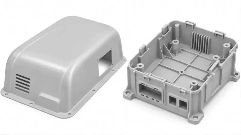
Thermoforming is commonly used for large covers, equipment housings, panels, trays, and liners. These parts often have broad surfaces and shell-like geometry. A large injection mold can require substantial investment because mold dimensions, clamping force, injection capacity, and handling requirements increase with part size.
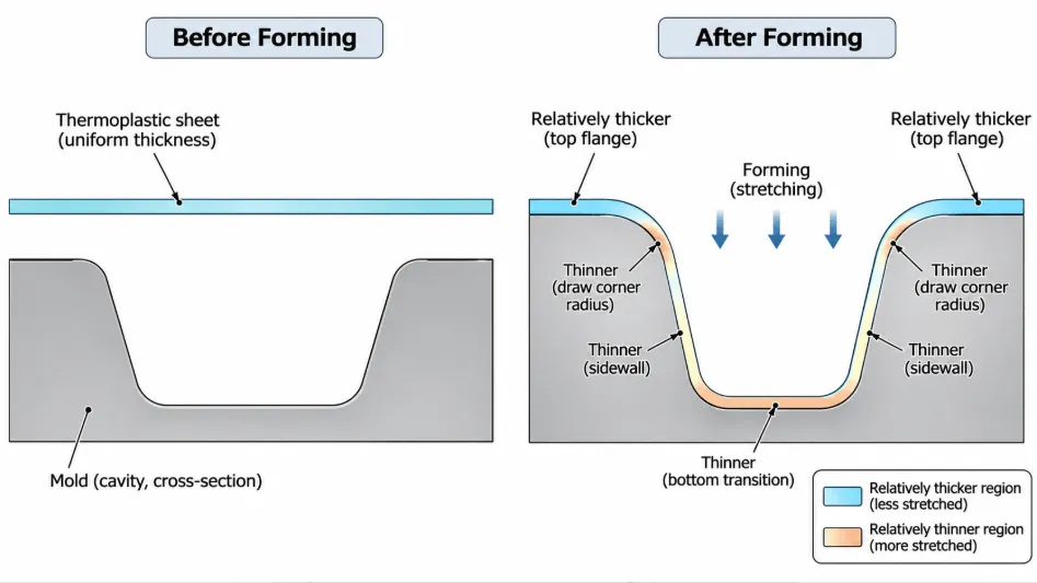
However, a large part is not automatically a good thermoforming candidate. Deep cavities, sharp corners, and narrow channels can stretch the sheet excessively. Material may become much thinner at corners or at the deepest sections than it was in the original flat sheet. Plug assistance, pressure forming, or a geometry revision may be needed.
Injection molding is more suitable when several functional features need to be integrated into one component. Ribs, bosses, snap fits, and complex interfaces can often be formed directly in the mold. Large injection-molded parts are also possible, but machine capacity, mold weight, and clamping force must be checked against the part envelope.
Consider a control-panel housing with a broad exterior surface, several mounting bosses, and precise connector openings. Thermoforming may be practical for the shell, but the mounting and connector features could require additional machining or hardware. Injection molding may integrate more of these features into the part, provided the tooling investment is justified.
How Does Wall Thickness Differ Between the Two Processes?
Thermoformed parts do not retain the original sheet thickness everywhere. As the heated sheet follows the mold surface, it stretches. Deep draws, corners, and areas where material is pulled in multiple directions are particularly vulnerable to thinning. Starting with a thicker sheet can increase material use without eliminating uneven distribution.
Injection molding gives the designer more direct control over nominal wall geometry because the cavity defines the part’s shape. Thick sections still need attention. They cool more slowly than thin walls and may shrink unevenly, leaving sink marks, internal voids, or warpage. Keeping wall sections reasonably uniform and coring out bulky areas can reduce these risks.
| Design feature | Thermoforming | Injection molding |
|---|---|---|
| Wall thickness | Varies with sheet stretching and draw depth | Defined by cavity geometry; affected by filling and cooling |
| Ribs | Broad formed ribs can add stiffness, but fine or deep ribs are more constrained | Can be molded directly into the part |
| Bosses | Often need additional hardware, bonding, or machining | Can be integrated into molded geometry |
| Snap fits | Some formed lips and undercuts are possible, but geometry is more constrained | Can be designed into the part, sometimes requiring side actions |
| Deep cavities | Risk of corner thinning and uneven material distribution | Depends on flow length, wall design, cooling, and ejection |
| Undercuts | May require movable tooling, flexible release, or redesign | Can use slides, lifters, or other mold mechanisms |
A thermoformed part does not have to be a featureless shell. Pressure forming and specialized tooling can produce ribs, louvers, returns, and some undercuts. The limits are set by feature depth, spacing, sheet thickness, and whether the formed part can release from the tool. Injection molding offers more options for integrated details, although thin walls can still be difficult to fill consistently.
What Draft Angles, Radii, and Undercuts Should You Consider?
Both processes need draft and radii, but the design concerns differ. Thermoformed parts must release from the tool after the sheet cools and contracts. Injection-molded parts must eject from the core and cavity without dragging, sticking, or damaging cosmetic surfaces.
For thermoforming, draft depends on whether the tool is male or female, as well as draw depth, surface texture, and material. Deeper features and textured surfaces need particular attention. Sharp inside corners should be avoided because they concentrate stretching and increase the risk of local thinning.
Injection molding draft is affected by wall depth, resin, surface texture, and ejection direction. Undercuts can be formed with slides or lifters, but these mechanisms add mold components, machining, and maintenance. If a feature can be redesigned to avoid a side action, the mold may be simpler and less expensive.
Which Process Costs Less? Tooling, Lead Times, and Break-Even Volume
Thermoforming usually requires less initial tooling investment because many applications use simpler, often single-sided tools. Injection molding generally needs a more involved core-and-cavity mold. Its higher upfront cost can be offset by lower unit costs when production volume is sufficient. Compare the cost of accepted parts, including the operations needed to make them ready for assembly.
How Do Thermoforming and Injection Molding Tooling Costs Compare?
Thermoforming tools may be made from aluminum, composite materials, or other materials selected for the required part quality and production volume. A simple shell with straightforward trim geometry may need relatively uncomplicated tooling. More demanding parts can require pressure-forming tools, plug assists, matched tools, trim fixtures, or movable sections.
Injection molding tools have to withstand repeated clamping and injection pressure while controlling filling, cooling, and ejection. Their cost is affected by:
- Mold size and part geometry
- Tool steel or aluminum selection
- Single-cavity or multi-cavity layout
- Runner and gate design
- Cooling system complexity
- Slides, lifters, and other side actions
- Surface texture and cosmetic requirements
- Expected tool life
The mold material is not fixed by the process. Aluminum injection molds can be suitable for prototypes, bridge tooling, or certain production runs. Steel molds may be more appropriate when tool life, production volume, or part geometry requires them.
For injection-molded parts, mold design and fabrication are major cost drivers. Reviewing the part before tooling begins can identify unnecessary side actions, difficult parting lines, and features that could be simplified.
Tooling Lead Times and Production Schedules
Thermoforming tools are often faster to produce because they may have fewer components and simpler machining requirements. Injection molding tooling can take longer when the mold needs multiple cavities, complex slides, detailed surface textures, or extensive cooling and ejection systems. Actual timing depends on the part and tool design.
The release sequence also differs:
| Project stage | Thermoforming | Injection molding |
|---|---|---|
| DFM review | Draw depth, sheet thickness, draft, and trim access | Wall thickness, draft, gate, cooling, shrinkage, and ejection |
| Tool design | Forming tool and trim strategy | Core, cavity, runner, cooling, and ejection |
| Tool fabrication | Often fewer complex tool features | May involve more machining, fitting, and tool components |
| Trial production | Forming temperature, material distribution, and trimming | Filling, packing, cooling, ejection, and dimensional checks |
| Production release | Formed-part and trim consistency | Process stability and molded-part repeatability |
A quicker forming tool may still leave substantial work after the part comes off the machine. Thermoformed parts may need a separate trim fixture and CNC programming. Injection-molded parts may need several trial cycles to resolve filling, shrinkage, or warpage.
When comparing schedules, use the date when acceptable, inspected parts can be shipped—not just the expected tool completion date.
How Do You Calculate the Break-Even Production Volume?
The break-even point is the quantity at which the total cost of the two processes becomes equal. Thermoforming may start with a lower tooling cost but have higher per-part trimming or machining costs. Injection molding usually needs more upfront investment, while its unit cost can fall as production volume increases.
A simplified cost comparison is:
Ctotal = T + Q × U
Where:
- T = tooling and setup cost
- Q = quantity of accepted parts
- U = cost per accepted part, including material, forming or molding, finishing, and inspection
If injection molding has a higher tooling cost but a lower unit cost, the break-even quantity is:
QBE = (TIM − TTF) / (UTF − UIM)
This formula applies when injection molding has both higher tooling cost and lower unit cost.
Illustrative example—not a market quotation:
| Cost item | Thermoforming | Injection molding |
|---|---|---|
| Tooling and setup | $8,000 | $40,000 |
| Cost per accepted part | $18 | $8 |
The break-even quantity is:
QBE = (40,000 − 8,000) / (18 − 8) = 3,200 parts
Below 3,200 parts, the simplified model favors thermoforming. Above that quantity, injection molding becomes less expensive under these assumptions.
When comparing supplier quotations, pay particular attention to trimming and machining costs for thermoformed parts, and mold maintenance and cycle time for injection-molded parts. These items can change the economics more than the initial tooling difference.
The example applies to custom formed parts such as equipment covers, housings, panels, and trays. It should not be applied indiscriminately to all thermoforming work: thin-gauge packaging, for example, can run at very high production volumes.
Which Materials Are Used in Thermoforming and Injection Molding?
Both processes use thermoplastics such as ABS, polycarbonate, polypropylene, polyethylene, and PET-based materials. The important distinction is the material form and grade: thermoforming starts with sheet, while injection molding starts with resin pellets. Two grades from the same polymer family may have different additives, processing behavior, and mechanical properties.
What Materials Are Suitable for Each Process?
A polymer name alone is not enough to approve a material. For a thermoformed enclosure, sheet behavior during deep drawing is just as important as its final impact strength. If the part will operate outdoors, UV resistance and long-term dimensional stability also need checking. Injection molding requires a grade with suitable melt flow, shrinkage, and mechanical properties for the finished geometry.
| Material | Thermoforming | Injection molding | Typical considerations |
|---|---|---|---|
| ABS | Common sheet material | Common resin | Impact resistance, stiffness, and appearance |
| Polycarbonate (PC) | Available in sheet grades | Common resin | Impact resistance and heat performance; forming conditions need control |
| PET / PETG | Common sheet materials | Available in suitable grades | Transparency, toughness, and forming behavior |
| HIPS | Common sheet material | Available | Cost-effective applications with moderate impact requirements |
| HDPE | Available in sheet form | Common resin | Chemical resistance, flexibility, and relatively high shrinkage |
| Polypropylene (PP) | Available in sheet form | Common resin | Chemical resistance, fatigue behavior, and forming conditions |
| PMMA (Acrylic) | Common sheet material | Available | Optical clarity and surface appearance; more brittle than some alternatives |
| PA (Nylon) | Special sheet applications | Common resin | Strength and wear resistance; moisture absorption affects dimensions |
This is a process-selection guide, not a substitute for checking a specific grade’s datasheet. For example, polycarbonate sheet used for a thermoformed enclosure may not have the same impact rating, flame-retardant package, or optical properties as a selected injection molding grade.
If a material change is being considered after prototyping, check the grade before approving the tooling or production route. A change within the same polymer family can still affect forming behavior, shrinkage, and part performance.
Material Performance in the Finished Part
Material selection should start with the part’s operating conditions. A protective cover may need impact resistance and UV stability. An electrical enclosure may require a specified flame-retardant grade. For a chemical-handling component, check compatibility with the actual fluid, concentration, temperature, and exposure time.
The forming process also affects what needs to be checked. Thermoforming stretches a sheet, so final thickness—and therefore local stiffness—can vary across the part. Injection molding creates flow and weld-line patterns. With fiber-filled grades, fiber orientation can influence shrinkage and warpage.
For critical applications, confirm the exact material grade, test method, environmental conditions, and acceptance criteria. Material data should be checked against the finished part’s actual assembly and service conditions.
Material Waste and Utilization
Thermoforming leaves a surrounding web or trim skeleton after the part is cut from the sheet. That scrap may be recyclable or reprocessable, depending on polymer type, contamination, degradation, and the sheet supplier’s process.
Injection molding can also generate waste through sprues, runners, gates, and rejected shots. Cold-runner scrap may sometimes be reground and reused within material and process limits; hot-runner systems can reduce runner waste.
For a meaningful sustainability comparison, look at actual material consumption and scrap recovery for the part. Neither process guarantees lower material waste across every application.
How Do Tolerances, Surface Finish, and Secondary Operations Compare?
Injection molding can provide consistent dimensions for features formed directly by a stable mold. Thermoforming presents different challenges on large surfaces because sheet stretching, cooling, and trimming affect the final geometry. Neither process has a single tolerance value that applies to every part; the critical question is whether the features controlling fit and assembly can be produced and inspected reliably.
Which Process Can Hold Tighter Dimensional Tolerances?
Injection molding can maintain consistent dimensions when resin, mold temperature, packing pressure, cooling, and ejection conditions are controlled. Molded dimensions still change with material shrinkage, fiber orientation, and wall thickness. The tool may need adjustment or compensation to meet the drawing.
Thermoformed dimensions are influenced by sheet gauge, material stretching, tool contact, cooling, springback, and post-forming shrinkage. Large panels and housings can be sensitive to temperature and geometry. A feature that contacts the tool directly may be easier to control than a dimension spanning a broad formed surface.
For either process, identify the dimensions that control fit and assembly. These often include:
- Mounting holes and locating features
- Connector openings
- Sealing surfaces
- Mating edges
- Interfaces with PCBs, fasteners, or internal components
If a formed or molded feature cannot reliably hold the required tolerance, CNC machining or another secondary operation may be needed.
Avoid applying the tightest tolerance to every dimension by default. Separate critical interfaces from non-functional surfaces, and use GD&T where it clarifies the datum structure and assembly relationship.
How Do Surface Finish and Cosmetic Quality Differ?
Thermoforming often reproduces the surface of the sheet and the tool-contact surface. The sheet may already have a texture, gloss level, or protective film. Pressure forming can produce more surface detail than basic vacuum forming, but the result still depends on sheet quality, tool finish, forming pressure, and material distribution.
Injection molding can reproduce a wide range of mold textures and polished finishes. The result is affected by mold finish, resin, gate location, flow behavior, and ejection. Weld lines, flow marks, sink marks, gate vestiges, and parting-line marks may appear in visible areas if the design and tooling are not planned carefully.
Specify cosmetic requirements by surface and function:
- Visible exterior face: Define the required texture, gloss, or color.
- Mating surface: Set the dimensional requirements that affect fit.
- Support-contact area: Decide whether witness marks are acceptable if they do not affect function.
- Sealing interface: Specify both surface condition and dimensional requirements.
Treating every surface as equally cosmetic can increase tooling and inspection costs without improving the product.
What Secondary Operations Are Required After Forming?
Thermoformed parts commonly need trimming because the formed sheet must be cut to its final outline. Accurate openings, mounting holes, and edges may then require CNC machining. Injection-molded parts often leave the mold closer to their final geometry, although gate removal, machining, hardware installation, or assembly may still be necessary.
| Operation | Thermoforming | Injection molding |
|---|---|---|
| Edge trimming | Common; often required to separate the part from the sheet | Usually limited to gate or runner removal |
| CNC machining | Used for accurate openings, slots, and edges | Used for features requiring tighter control than molding alone provides |
| Drilling | May be needed for mounting holes | Often avoidable if holes can be molded into the part |
| Bonding | Used to join formed sections or attach features | Used when multiple molded components form an assembly |
| Hardware and inserts | Often installed after forming | Can be installed after molding or insert-molded |
| Assembly | May be needed for multi-piece shells and covers | May use snap fits, screws, inserts, or secondary assembly |
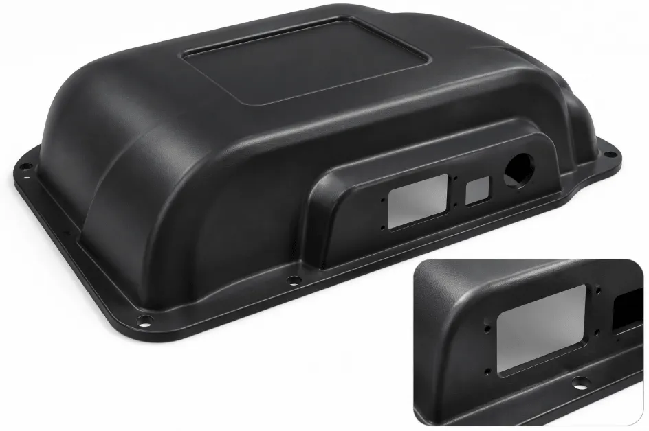
The trim strategy should be considered during design. If mounting holes are cut after forming, the trim fixture needs stable locating surfaces. If two formed sections are bonded together, joint geometry, adhesive compatibility, and assembly tolerances become part of the manufacturing plan.
For parts requiring accurately machined openings, mounting faces, or edges, CNC machining services may be relevant as part of the overall manufacturing route.
What Defects Should Be Checked During Production?
Defect inspection is more useful when it looks for the cause as well as the visible symptom. In thermoforming, uneven material distribution and heating can lead to local thinning or warpage. In injection molding, wall transitions, filling, packing, and cooling are common areas to investigate when dimensional or cosmetic defects appear.
| Process | Common defect | Likely cause to investigate |
|---|---|---|
| Thermoforming | Local thinning | Excessive draw depth, sharp corners, or poor material distribution |
| Thermoforming | Webbing or wrinkles | Sheet sag, material flow, or tool geometry |
| Thermoforming | Bubbles or blisters | Moisture, trapped air, or overheating |
| Thermoforming | Warpage or springback | Uneven cooling, residual stress, or material recovery |
| Injection molding | Sink marks | Thick sections, uneven cooling, or insufficient packing |
| Injection molding | Flash | Parting-line issues, mold damage, or inadequate clamping |
| Injection molding | Weld lines | Flow fronts meeting around holes or other obstacles |
| Injection molding | Warpage | Uneven shrinkage, cooling, or fiber orientation |
For thermoformed parts, inspect material distribution around deep draws and corners, along with trim-line consistency. For injection-molded parts, pay attention to wall transitions, gate location, weld-line positions, and cooling balance. Inspection should focus on the areas most likely to affect fit, function, appearance, and assembly.
When Should You Choose Thermoforming or Injection Molding?
Thermoforming deserves early consideration for large, shell-like parts with relatively simple geometry and a need to limit initial tooling investment. Injection molding is usually a stronger candidate when a part needs detailed molded-in features, repeatable interfaces, and production quantities that justify a more complex mold. The examples below help screen a design before requesting detailed quotations.
When Is Thermoforming the Better Choice?
Thermoforming is often suitable when a part is large relative to its wall thickness and does not need many detailed features on both sides. Typical examples include equipment covers, machine guards, instrument panels, trays, liners, and large housings.
Consider thermoforming when:
- The part has broad, shell-like geometry.
- The design has limited ribs, bosses, and integrated fastening features.
- Initial tooling investment is a major constraint.
- The design may change during product development.
- Required tolerances can be achieved through forming and planned trimming.
- A large injection mold would require substantial machine capacity or investment.
The main design concerns are local thinning, deep-draw limits, trim variation, and the work needed to add mounting or assembly features. A formed equipment cover may be practical, for example, but its mounting holes and connector openings may need CNC machining to achieve the required positions.
When Is Injection Molding the Better Choice?
Injection molding is often preferable when a part needs complex three-dimensional geometry, repeatable molded features, or a high degree of integration. Common applications include electronic housings, connectors, clips, brackets, and control components that combine structural and assembly features.
Consider injection molding when:
- The design includes ribs, bosses, snap fits, or detailed features.
- Both sides of the part need controlled geometry.
- Critical dimensions need consistent reproduction across batches.
- Production volume can justify the tooling investment.
- Automated production and short cycle times can reduce unit cost.
- The design is sufficiently mature to commit to the mold.
Tooling changes can become expensive after steel is cut. A design with thick sections, poor gate placement, or difficult ejection can also create recurring defects. Before finalizing the production tool, review mold filling, cooling, shrinkage, and assembly fit—not just the fit and function of a prototype.
Mastars’ injection molding services support plastic part production alongside tooling and related manufacturing operations.
A Practical Process Selection Matrix
Use this matrix to identify which process deserves closer evaluation. It is an initial screening tool; the final decision still needs to account for the actual geometry, production quantity, and post-processing requirements.
| Project requirement | Process to evaluate first | Why |
|---|---|---|
| Large, shallow shell or cover | Thermoforming | Lower tooling burden for many large formed parts |
| Large thin-wall panel | Thermoforming | Sheet forming may be more practical than a large injection mold |
| Complex molded-in ribs and bosses | Injection molding | Features can be integrated into the cavity |
| Snap fits and detailed assembly features | Injection molding | More options for molded functional geometry |
| Frequent design changes | Often thermoforming | Tool changes may be simpler, depending on tool design |
| High repeat production | Often injection molding | Tooling investment can be spread across more parts |
| Tight mounting-hole locations | Either, with secondary machining if needed | Critical interfaces may need CNC control |
| Low initial tooling budget | Often thermoforming | Forming tools are generally less complex |
| Deep draw with tight wall-thickness requirements | Requires detailed review | Plug assistance, pressure forming, or a different process may be needed |
Before making the decision, check these project details:
- Part envelope: Does the part fit the available machine and tooling capacity?
- Draw depth: Where could the sheet become too thin?
- Integrated features: Which ribs, bosses, snap fits, threads, or undercuts are essential?
- Assembly dimensions: Which datums, mating surfaces, and openings control fit?
- Lifetime quantity: Include expected revisions, replacement demand, and forecast changes.
- Post-processing: Account for trimming, CNC machining, bonding, hardware, finishing, and inspection.
- Total part cost: Compare tooling, unit cost, scrap, rework, and logistics.
How Should You Prepare a Plastic Part for Manufacturing?
A useful manufacturing quotation needs more than a 3D model. The supplier needs to understand the material, critical dimensions, expected quantity, appearance requirements, and assembly conditions. These details help establish whether the part is feasible, which process should be evaluated, and where tooling or secondary operations may affect cost.
What Information Should You Include in an RFQ?
Prepare the following information where available:
- 3D CAD files: STEP or IGES files are useful for geometry review.
- 2D engineering drawings: Include dimensions, GD&T, datums, and notes that cannot be inferred from the model.
- Material requirements: Specify the resin family and grade if already selected. Include flame-retardant, UV, food-contact, or other requirements where applicable.
- Production quantity: Provide prototype quantity, initial order quantity, annual demand, and estimated lifetime volume.
- Critical dimensions: Identify mounting holes, sealing surfaces, mating interfaces, and other dimensions that affect fit or function.
- Surface requirements: Specify visible surfaces, texture, gloss, color, and acceptable witness marks.
- Assembly details: Include fasteners, inserts, bonded joints, PCB or connector interfaces, and any required assembly sequence.
- Inspection requirements: State whether first-article inspection, dimensional reports, material certificates, or functional checks are required.
If the design is still under development, a preliminary CAD file and approximate quantity are enough to start a process discussion. The remaining specifications can be clarified as the design matures.
What Should Be Reviewed Before Tooling Starts?
A DFM review should establish whether the geometry can be made consistently and whether the selected process can meet the functional requirements.
For thermoforming, review draw depth, draft, corner radii, sheet thickness, material distribution, trim lines, and access for CNC machining. For injection molding, check nominal wall thickness, ribs, bosses, undercuts, gate location, cooling, shrinkage, ejection, and parting lines.
The review should also establish how critical dimensions will be inspected. A mounting hole may be formed or molded close to its nominal position, but if its location controls assembly, a dedicated machining or inspection strategy may be more reliable.
How Do You Transition from Prototype to Production?
A prototype helps confirm fit, form, appearance, assembly, and basic function. It may not reproduce the final production material, forming history, shrinkage, surface condition, or process variation. Production therefore needs its own validation before the design is released for repeat manufacturing.
A typical transition includes:
Prototype → Design Review → DFM → Tooling → Trial Production → First Article Inspection → Production Validation → Repeat Production
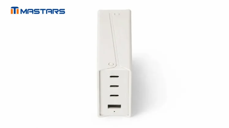
The multi-port USB charger enclosure project illustrates why prototype checks matter before committing to injection tooling. Prototype samples were used to assess USB-C openings, connector positioning, PCB accommodation, and assembly relationships. These checks help identify interface problems while design changes are still less costly.
For products combining rigid and flexible components, material compatibility and the interface between molding stages need attention. In the Bioness rehabilitation device project, staged overmolding was used to combine rigid and flexible material sections. The project illustrates why material compatibility and interface geometry need to be reviewed during development.
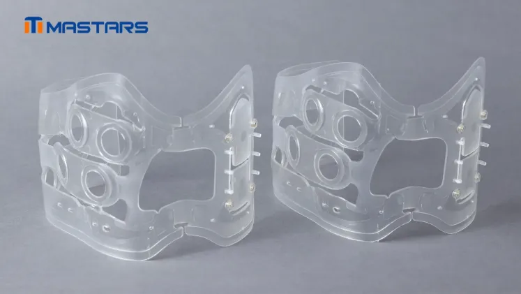
Mastars supports plastic product development through rapid prototyping, plastic tooling, injection molding, CNC machining, and assembly. Coordinating these stages through one manufacturing partner can reduce handoffs between prototype development, tooling, production, and downstream operations.
Production release should confirm that the process can repeatedly meet drawing and inspection requirements. First-article approval is one step; ongoing production still needs process monitoring, dimensional checks, and a clear response plan for deviations.
Conclusion
Thermoforming is often a practical choice for large, thin-walled parts with simpler geometry and lower initial tooling requirements. Injection molding is usually better suited to detailed components with integrated features and repeat production that can justify the mold investment.
For a custom plastic housing, first identify which features can be formed directly and which will need machining, hardware, or assembly. Then compare tooling investment against the expected cost of accepted, finished parts. This gives the project team a more useful basis for choosing a process than relying on a general production-volume threshold.
A plastic part may need more than one manufacturing process to reach its final form. Mastars brings together prototyping, plastic tooling, injection molding, CNC machining, and assembly, helping reduce coordination between development and production.
Send your 3D CAD files, drawings, material requirements, critical dimensions, and estimated quantities. If the design is still preliminary, rough information is fine to start. Include any assembly interfaces or surface requirements that could affect the manufacturing route.
Get a Quote to discuss your project and reduce the time spent coordinating suppliers.
FAQs

Often, for large custom parts and lower production volumes. Thermoforming generally has lower tooling costs, but trimming, CNC machining, bonding, and assembly can increase the cost of each finished part. Injection molding requires more upfront investment, but its unit cost may become lower as production volume increases. Compare the complete cost of accepted parts rather than mold price alone.
There is no universal break-even quantity. It depends on the part, tooling cost, cycle time, material use, and secondary operations. Some projects reach the break-even point at a few thousand parts; others favor thermoforming at higher quantities, particularly when parts are large or need extensive post-processing. Thin-gauge packaging is a separate high-volume thermoforming application.
Sometimes, on selected features, but the processes have different dimensional constraints. Thermoforming is affected by sheet stretching, cooling, springback, and trimming. Injection molding is affected by shrinkage, cooling balance, gate location, and material behavior. Critical holes, mounting points, and mating surfaces may need secondary machining with either process.
Yes. Suitable grades are available for both, but thermoforming uses sheet grades while injection molding uses grades designed for melt flow and cavity filling. The grades may differ in additives, impact performance, flame rating, or processing requirements. Confirm the exact grade against the part's service conditions before approving the material.
It can produce complex contours, but some features are more difficult than with injection molding. Pressure forming and specialized tooling can create detailed surfaces, formed ribs, and some undercuts. Deep narrow features, thick bosses, and complex snap-fit structures may require additional tooling, machining, bonding, or a different process.
No. Cleanroom production is an environmental and process-control requirement, not a forming method. Both thermoforming and injection molding can be performed in controlled environments when the facility, material handling, packaging, and contamination controls meet the project specification. Medical or food-contact applications also require review of the exact material grade and applicable regulatory requirements.
Yes. CNC machining, 3D printing, or other prototype methods can help check fit, form, assembly, and function before tooling. However, a prototype may not reproduce the final molded material, shrinkage, surface finish, or production variation. Confirm critical interfaces and production-specific risks before approving the mold design. A rejected sample is useful feedback if it identifies what needs to change before production.
 Headquarters


