



 English





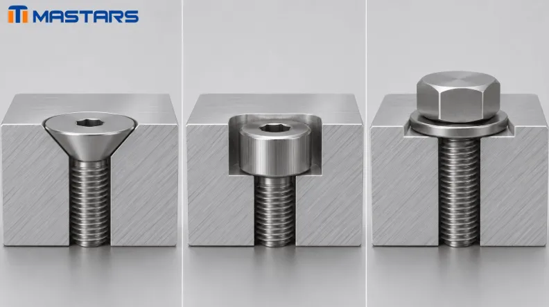
A countersink is a conical recess designed for a flat-head screw, while a counterbore is a cylindrical, flat-bottom recess that accommodates a cylindrical-head fastener, such as a socket head cap screw. The right choice depends on the fastener head, the required seating surface, available material thickness, and how the joint will be assembled.
Both features allow a fastener to sit below or flush with the surrounding surface, but they are not interchangeable. A countersink relies on contact between matching conical surfaces. A counterbore provides a flat bearing surface and clearance for the screw head. Choosing the wrong geometry can lead to poor seating, insufficient material around the hole, or interference with adjacent components.
The sections below focus on fastener selection, drawing requirements, material behavior, and the machining checks that help prevent these problems.
Countersink vs Counterbore: Key Differences
The main difference between a countersink and a counterbore is the shape of the recess and the fastener it accommodates. A countersink has an angled, conical seat for a flat-head screw. A counterbore has a larger cylindrical opening with a flat bottom for a cylindrical-head screw.
| Feature | Countersink | Counterbore |
| Recess geometry | Conical | Cylindrical, flat-bottom |
| Typical fastener | Flat-head screw | Socket head cap screw |
| Seating surface | Angled | Flat |
| Common purpose | Flush or near-flush mounting | Recessing a cylindrical screw head |
| Main dimensions | Major diameter and included angle | Recess diameter and depth |
| Typical machining tool | Countersink cutter | Counterbore tool or end mill |
Countersink Hole Geometry
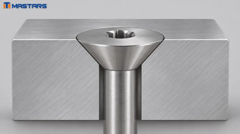
A countersink hole has a conical recess around a smaller pilot or clearance hole. Its included angle must match the screw head geometry closely enough to provide proper contact. When correctly dimensioned, the screw head can sit flush with the part surface, reducing protrusion and helping maintain a smooth external profile.
The countersink major diameter depends on the screw head dimensions, included angle, and required seating position. For a fixed angle and pilot-hole diameter, increasing the countersink depth increases the major diameter. This relationship matters when the hole is close to an edge, a thin wall, or another feature. Excessive material removal can leave a narrow rim around the recess and reduce local strength.
Counterbore Hole Geometry
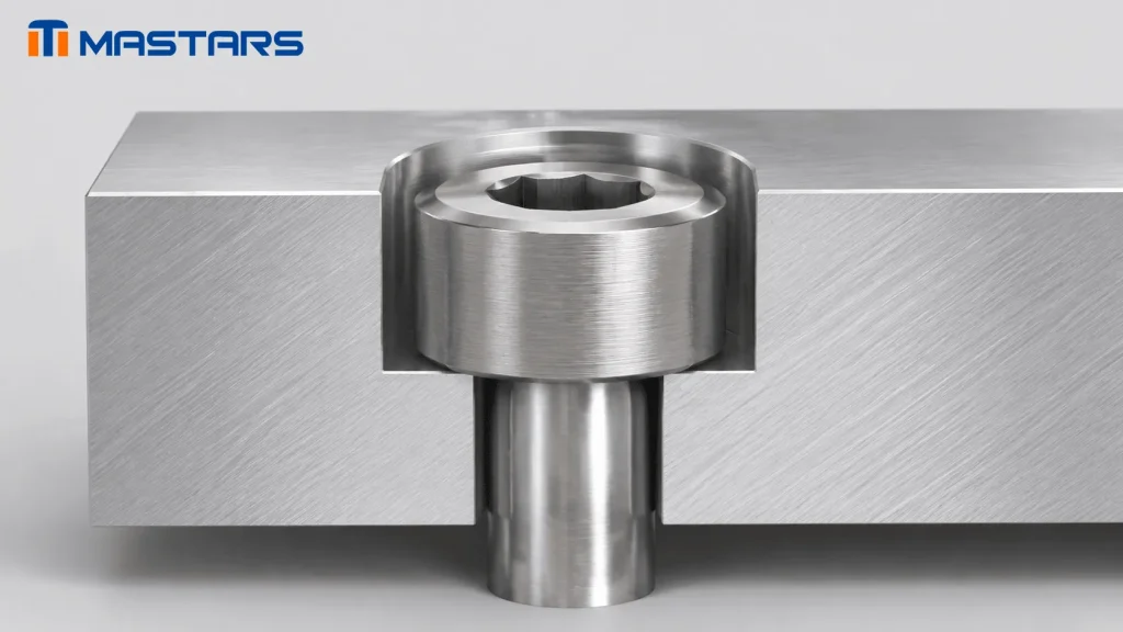
A counterbore is a stepped hole with a larger cylindrical recess above a smaller clearance hole. Its flat bottom provides a bearing surface for a cylindrical screw head, allowing the head to sit below the part surface while keeping the fastener axis aligned with the clearance hole.
The two key dimensions are the counterbore diameter and depth. The diameter must provide enough clearance for the screw head, while the depth determines how far the head sits below the surface. Unlike a countersink, a counterbore does not depend on matching an angled screw-head surface.
When Should You Use a Countersink, Counterbore, or Spotface?
Choose a countersink when the design calls for a matching flat-head fastener and a flush surface. Use a counterbore when a cylindrical-head screw needs to sit below the surface. A spotface is suitable when the main requirement is a flat, clean bearing area rather than full screw-head clearance.
| Feature | Best suited for | What to check |
| Countersink | Flat-head screws and flush mounting | Screw angle, major diameter, edge distance |
| Counterbore | Cylindrical-head screws recessed below the surface | Head clearance, recess depth, remaining material |
| Spotface | Creating a flat bearing area around a hole | Flatness, diameter, surface condition |
Spotface vs Counterbore
A spotface is a shallow, flat-bottomed machined area around a hole. It creates a more uniform seating surface for a fastener or washer, particularly when the original part surface is rough, angled, or irregular. A counterbore generally provides greater depth and enough diameter to recess the fastener head.
The distinction is functional. If the screw head must sit below the surrounding surface, a counterbore is usually appropriate. If the fastener only needs a flat surface to bear against, a spotface may remove less material and be the simpler feature.
Can a Counterbore Replace a Countersink?
Usually not without changing the fastener or joint design. A flat-head screw is designed to seat against a conical surface, whereas a counterbore provides a flat bottom. The two surfaces do not create the same contact condition, so substituting one recess for the other can cause poor seating or concentrated contact.
A design change may be possible if the fastener type also changes and the surrounding geometry allows it. Check the screw head, load path, available thickness, and assembly clearance before making the substitution.
How to Match Recess Dimensions to Fasteners
Countersink and counterbore dimensions should be taken from the selected fastener specification, not estimated from the nominal thread size. The screw head diameter, head angle, clearance requirement, and intended seating position determine the recess geometry. Confirm the actual fastener series before releasing the drawing.
Countersink Angles: 82°, 90°, or 100°?
The included angle of a countersink must match the fastener head angle. 82°, 90°, and 100° are common examples, but none should be treated as a universal default. The correct angle depends on the screw standard, regional practice, and the specific fastener being used.
For example, 82° flat-head screws are common in inch-based applications, while 90° designs are used in many metric applications. Some specialized fasteners use other angles. Always check the manufacturer’s dimensional drawing or the applicable fastener standard.
ISO 10642:2026 specifies metric hexagon socket countersunk head screws with reduced loadability, covering steel and stainless-steel fasteners with coarse-pitch threads from M2 to M20 and product grade A. It also calls attention to alignment between the countersunk screw head and the bearing surface. This standard describes a particular fastener type; it is not a universal specification for every countersink geometry.
How to Specify Countersink and Counterbore Dimensions
A complete hole specification should identify the through-hole or pilot-hole diameter, recess dimensions, and any relevant positional or geometric requirements. The callout must leave little room for interpretation by the machinist or inspector.
For example, the following are illustrative formats:
- Countersink:⌀6.6 THRU, ⌵ ⌀12 × 90°
- Counterbore:⌀6.6 THRU, ⌴ ⌀11 × 6 DEEP
- Spotface:⌀6.6 THRU, SF ⌀11
These examples are not universal callout templates. Symbol use, dimension order, depth notation, and required annotations depend on the drawing standard and CAD system used by the project. If the recess has a tight relationship to a mating component, include the necessary position or datum references rather than relying on diameter and depth alone.
Engineering Drawing Symbols and Callouts
Countersink and counterbore features use different drawing symbols because they describe different recess geometries. A drawing should identify the feature type and provide the dimensions needed to manufacture and inspect it. Where hole location or orientation affects assembly, the drawing should also define the relevant geometric tolerances.
Countersink, Counterbore, and Spotface Symbols
Common mechanical drawing notation includes:
| Feature | Common symbol or abbreviation |
| Countersink | ⌵ |
| Counterbore | ⌴ |
| Spotface | SF |
The exact presentation should follow the drafting standard specified for the project. ASME Y14.5-2018 (R2024) provides requirements and practices for dimensioning and tolerancing in engineering drawings and digital product definitions. It establishes rules and practices for defining and interpreting GD&T; consult the applicable standard and company drawing conventions for the complete notation requirements.
What Should a Complete Callout Include?
A useful callout should communicate the feature geometry and its relationship to the rest of the part. Depending on the application, include:
- Through-hole or pilot-hole diameter
- Countersink major diameter and included angle
- Counterbore diameter and depth
- Spotface diameter, where applicable
- Hole quantity and pattern
- Position or orientation tolerances when required
- Relevant datum references and surface requirements
For a mounting hole near a gasket or sealing interface, hole position can be just as important as recess size. The fastener must clear the mating component while leaving the sealing surface intact. A dimensionally correct recess does not compensate for a hole pattern that shifts the assembled parts out of alignment.
Material and Geometry Considerations
The same recess geometry can behave differently across aluminum, stainless steel, and engineering plastics. Material strength, ductility, wall thickness, and surface condition affect tool selection and the risk of burrs, deformation, cracking, or local loss of stiffness. Review the part section and fastener load before setting the recess depth.
Aluminum and Stainless Steel
Aluminum is relatively easy to machine, but thin sections can deform under clamping pressure or cutting forces. A deep counterbore in a thin mounting flange can leave little material beneath the recess. A countersink near an edge can also reduce the width of the remaining rim. Check the section thickness before finalizing either feature.
Stainless steel requires attention to cutting conditions. Austenitic grades such as 304 and 316 can work-harden when the tool rubs instead of cutting cleanly. A dull cutter, excessive dwell, or an unsuitable feed can worsen the condition and affect the finish. Use sharp tooling and stable cutting conditions, and avoid allowing the tool to dwell on the finished seat.
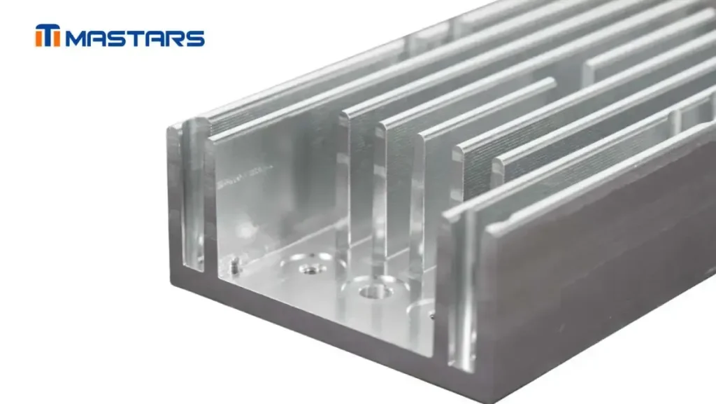
In Mastars’ 6060-T6 aluminum heatsink machining, thin fins and base-flatness requirements make fixture pressure and cutting strategy important. Standard clamping can damage delicate fins or distort the base; soft-jaw tooling, vacuum fixtures, and tailored cutting strategies help control these risks. The same workholding principles are relevant when machining recessed features near thin sections, although this project is not presented as a countersink or counterbore example.
Engineering Plastics
Plastic parts need a different approach because their stiffness, toughness, and long-term deformation behavior vary widely by material. A countersunk fastener can introduce radial forces into the surrounding material. In brittle plastics, this may cause cracking; in softer materials, tightening load and long-term creep can affect the seating condition.
A counterbore with a washer or a larger bearing surface may distribute the load more effectively in some designs, but it is not automatically the better choice. Check the fastener torque, material grade, local wall thickness, and whether the joint must maintain preload over time. For highly loaded joints, consider a metal insert or a separate load-spreading feature.
CNC Machining: Tools, Sequence, and Common Defects
Countersinks, counterbores, and spotfaces use different cutting tools and machining strategies. A countersink cutter forms the conical seat; a counterbore tool or end mill creates the cylindrical recess; and a spotfacing tool or end mill produces the shallow flat area. Tool access, rigidity, material, and feature location influence the final result.
Tool Selection and Machining Sequence
The tool should match the required geometry and the available access. A dedicated countersink cutter can produce the specified angle, while a CNC interpolation path may be suitable when the feature geometry or tooling setup calls for it. Counterbores are commonly machined with a counterbore tool or an end mill, depending on diameter, depth, and access.
A typical machining sequence is:
- Establish the pilot or clearance hole.
- Machine the countersink, counterbore, or spotface to the specified dimensions.
- Deburr the hole edges without damaging the seating surface.
- Inspect the feature before any finishing process that could change its dimensions.
The order may change with the part geometry, setup, and process route. For example, a feature may need to be machined in the same setup as its locating hole to maintain positional accuracy. If the part is repositioned, the datum scheme and workholding must preserve the required relationship.
Common Machining Problems
Several defects can affect fastener seating even when the nominal hole diameter is correct.
| Problem | Likely cause | What to check |
| Uneven countersink seat | Tool runout, poor alignment, unstable setup | Concentricity, cutter condition, fixture rigidity |
| Burrs around the recess | Dull tool, unsuitable feed, poor deburring | Edge condition and seating contact |
| Incorrect counterbore depth | Tool offset error, setup variation, tool wear | Depth measurement and tool setting |
| Chatter or poor surface finish | Insufficient rigidity, unsuitable cutting conditions | Workholding, tool overhang, cutting strategy |
| Distorted thin section | Excessive clamping or cutting force | Fixture contact and machining sequence |
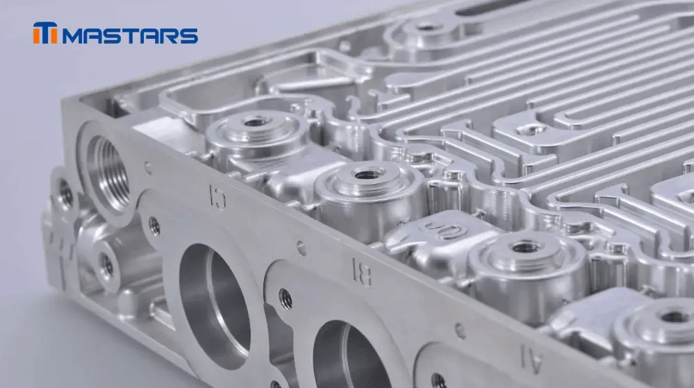
Mastars’ aluminum cold plate work illustrates why hole locations and adjacent surfaces must be considered together. The part includes mounting features, cavities, and gasket interfaces that must align during assembly. Its process uses rigid fixturing, multi-axis milling, precision deburring, CMM checks of critical features, and leak testing. These controls are relevant to machined mounting interfaces, but the project should not be mistaken for a documented countersink or counterbore job.
Inspection and Production Repeatability
Inspection should verify the dimensions that control fastener seating and assembly, rather than relying on a single hole-diameter measurement. For a countersink, the key checks are the major diameter, included angle, and position. For a counterbore, inspect the recess diameter, depth, and position relative to the clearance hole and part datums.
Inspection Methods for Each Feature
The inspection method depends on the feature size, tolerance, and required reporting level.
| Feature | Critical dimensions | Possible inspection methods |
| Countersink | Major diameter, included angle, position | Optical measurement, CMM, suitable countersink gauges |
| Counterbore | Diameter, depth, position | Bore gauges, depth gauges, CMM |
| Spotface | Diameter, depth or surface condition, position | Calipers or bore gauges where suitable, depth measurement, CMM |
A plug gauge can confirm aspects of a hole’s size, but it does not by itself verify countersink angle, counterbore depth, or feature position. If the fastener must sit flush or align with a mating component, inspect the seating geometry and location as well.
Prototype Inspection vs Production Control
Prototype inspection should confirm that the selected fastener fits, seats correctly, and clears adjacent components. It is also the time to check whether the drawing dimensions reflect the actual assembly requirement. A prototype that assembles successfully does not automatically establish a stable production process.
For repeat orders, inspection planning should identify which dimensions need routine monitoring and how measurement results will be recorded. Critical hole features may require first-article inspection and subsequent checks based on quantity, tolerance, process stability, and the risk of assembly failure. The inspection plan should be agreed before production rather than added after dimensional problems appear.
What Affects Countersink and Counterbore Machining Cost?
Machining cost depends on more than the number of holes. Material, recess size and depth, tolerance, tool access, setup requirements, and finishing all affect cycle time and inspection effort. Tight positional relationships or deep recesses in thin sections may require additional workholding and process control.
The main cost factors include:
- Feature quantity and pattern:More holes increase machining and inspection time, especially when several setups are needed.
- Material:Stainless steel and some engineering plastics may require different tooling and cutting conditions from aluminum.
- Recess dimensions:Large diameters, deeper counterbores, and tighter tolerances can increase cycle time.
- Part geometry:Thin walls, limited tool access, and nearby sealing or mating surfaces can complicate fixturing and machining.
- Surface finishing:Anodizing, plating, or other coatings may affect critical dimensions and fastener fit.
- Inspection requirements:CMM measurement, first-article reporting, and documented traceability add time but may be necessary for critical interfaces.
If a recessed feature is part of a visible or mating surface, specify the required finish and dimensional condition after finishing. For anodized aluminum, for example, account for coating growth when sizing holes and seating surfaces. The dimensional effect depends on the anodizing process and which surfaces are masked or treated, so critical interfaces should be defined on the drawing.
Conclusion
The choice between a countersink and a counterbore comes down to the fastener head, seating condition, and available material. Use a countersink with a matching flat-head screw when a flush surface is required. Choose a counterbore for a cylindrical-head fastener that needs a flat bearing surface below the part face. A spotface is usually sufficient when the goal is to create a flat seating area without recessing the full screw head.
Before machining, confirm the fastener dimensions, recess geometry, remaining wall thickness, hole position, and inspection requirements. These checks help prevent seating problems and avoid removing more material than the joint requires.
Send Mastars your 3D CAD model, engineering drawing, material, quantity, and required finish for a CNC machining review and quote. Include critical hole dimensions, fastener specifications, positional tolerances, and any flush-mounting or assembly requirements. If the design is still being finalized, preliminary drawings are useful for an initial assessment.
FAQs

Yes. Anodizing changes the surface dimensions of aluminum parts, and the effect depends on the coating process and thickness. If a countersink or counterbore is a critical seating feature, define whether it should be masked or machined with the coating allowance considered. Confirm the final fastener fit after finishing.
Use a method suited to the feature and its tolerance. A depth gauge or CMM can check counterbore depth; optical measurement or a suitable gauge can help verify countersink geometry. A basic plug gauge alone cannot confirm recess depth, countersink angle, or hole position.
Yes. Countersinks can also be used to create a chamfer or remove a sharp edge around a hole. If the feature is intended only for deburring, specify the required edge break rather than assuming a standard fastener countersink.
There is no universal minimum that applies to every part. The required remaining thickness depends on the material, load, fastener size, edge distance, and surrounding geometry. For example, a 3 mm plate with a 2.5 mm-deep counterbore leaves 0.5 mm of material beneath the recess. This is a geometric illustration, not a recommended design limit. Structural adequacy must be evaluated for the actual joint.
Provide the 3D CAD file and 2D drawing where available, along with material grade, quantity, finish, and target delivery date. Identify the fastener type and any critical countersink angle, recess diameter, counterbore depth, hole-position tolerance, or assembly requirement. Preliminary information is enough to start a discussion.
 Headquarters


