


CNC Turning Manufacturing Process and Optimization of Precision Electronic Connector Components


1. Introduction
With the rapid iteration of consumer electronics, semiconductor equipment, and industrial control electronic systems, electronic components are continuously developing toward miniaturization, high precision, high conductivity, and strong environmental adaptability. As a core basic electronic component, precision electronic connectors undertake the critical functions of signal transmission, current conduction, and mechanical connection between electronic equipment modules. Their dimensional accuracy, surface quality, and structural stability directly determine the operating stability and service life of the entire electronic system. In the manufacturing process of cylindrical and rotary electronic connector parts, CNC turning technology has become the mainstream processing method by virtue of its high machining accuracy, excellent batch repeatability, and flexible processing adaptability.
CNC turning is an automated subtractive manufacturing technology that relies on computer numerical control systems to drive machine tools. During the processing, the workpiece rotates at a high speed, and the fixed cutting tool performs linear or curved feed motion to remove redundant materials, so as to form rotary parts with precise geometric dimensions. Compared with traditional manual lathe processing, CNC turning effectively eliminates human operation errors, realizes micron-level dimensional tolerance control, and is highly compatible with metal conductive materials and engineering insulating materials commonly used in electronic connectors. At present, more than 70% of cylindrical precision electronic connectors in the electronics industry are manufactured by CNC turning, including conductive pins, connector terminals, insulating connecting sleeves, and sealing fastening parts.
Electronic connectors have extremely stringent manufacturing standards due to their service scenarios. For high-end communication electronic connectors, the dimensional tolerance of key structures needs to be controlled within ±0.005 mm, the surface roughness must be lower than Ra 0.8 μm, and the parts need to maintain stable electrical conductivity and corrosion resistance in high-temperature, humid, and electromagnetic interference environments. These technical indicators put forward higher requirements for CNC turning processing technology, including material selection, cutting parameter setting, tool selection, clamping scheme, and post-processing technology. This paper takes a typical brass precision conductive connector pin as the processing research object, comprehensively analyzes the entire CNC turning processing flow of electronic components, discusses the key technical difficulties in the processing process, and puts forward targeted optimization schemes to provide technical reference for the high-efficiency and high-precision batch production of electronic connector parts.
2. Overview of CNC Turning Technology and Electronic Connector Characteristics
2.1 Basic Principle and Technical Advantages of CNC Turning
The working principle of CNC turning is based on digital programming control. Engineers draw the part model through CAD software, convert the processing path into executable G codes by CAM programming software, and import the program into the CNC lathe control system. The system accurately controls the spindle rotation speed, tool feed rate, cutting depth, and tool change sequence to complete automatic cutting processing. The core motion logic is that the workpiece rotates around the spindle axis, and the turning tool moves along the axial and radial directions to complete turning operations such as outer circle, inner hole, end face, thread, and groove processing.
In the field of electronic component processing, CNC turning has irreplaceable technical advantages. First of all, it has ultra-high processing accuracy. Modern high-precision CNC lathes can achieve a dimensional tolerance of ±0.003 mm, which meets the miniaturization processing requirements of micro electronic connectors. Secondly, the batch consistency is excellent. The digital control mode ensures that the dimensional deviation of parts in the same batch is less than 0.01 mm, avoiding poor contact caused by size differences of connectors. In addition, CNC turning has strong material adaptability, which can process conductive metals such as brass, phosphor copper, and aluminum alloy, as well as insulating engineering plastics such as POM and PEEK, covering all common materials of electronic connectors. Finally, the processing efficiency is high. The automated processing mode reduces manual intervention, and the continuous processing cycle of a single connector pin can be controlled within 2 minutes, which is suitable for large-scale industrial production.
2.2 Structural and Processing Characteristics of Precision Electronic Connector Pins
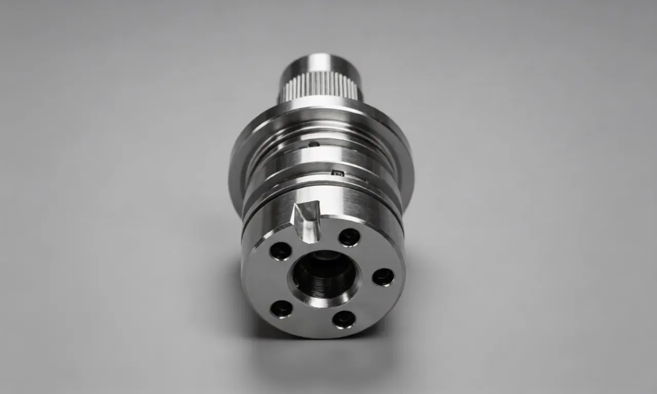
The research object of this paper is a brass conductive connector pin for automotive electronic control modules. This component is a typical rotary electronic part, with an overall length of 12.5 mm, a maximum outer diameter of 3.2 mm, and a minimum shaft diameter of 1.5 mm. The part has a stepped shaft structure, including a clamping fixing section, a conductive connecting section, and a guiding insertion section. The surface is required to be smooth and burr-free to ensure low contact resistance during electrical connection. The key technical parameters of the part are shown in Table 1.
Technical Indicators | Parameter Requirements | Technical Purpose |
Overall Length Tolerance | ±0.02 mm | Ensure Assembly Matching Accuracy |
Shaft Diameter Tolerance | ±0.005 mm | Reduce Contact Clearance |
Surface Roughness | ≤Ra 0.8 μm | Lower Contact Resistance |
Verticality Tolerance | 0.01 mm | Avoid Insertion Deviation |
Material Hardness | 85-95 HV | Prevent Deformation During Insertion |
Different from traditional mechanical rotating parts, electronic connector pins have unique processing characteristics. On the one hand, the parts are small in size and thin in wall, and the slender shaft structure is prone to bending deformation under cutting force, resulting in dimensional deviation. On the other hand, the surface quality requirements are extremely strict. Burrs, tool marks, and surface scratches will increase electrical contact resistance, cause signal attenuation, and even lead to short circuit failure of electronic equipment. In addition, the connector needs to have good corrosion resistance, so the surface needs to be plated with a thin layer of nickel and gold after turning, which requires the turning blank to have a flat and dense surface without microscopic cracks.
3. Material Selection and Preprocessing of Electronic Connector Pins
3.1 Material Selection Basis
Material performance is the fundamental factor affecting the processing quality and service performance of electronic connectors. Considering the electrical conductivity, machinability, corrosion resistance, and cost of connector pins, H59 brass is selected as the raw material for this part. H59 brass is an alloy material composed of copper and zinc, with a copper content of 57%-60%. It has excellent electrical conductivity (conductivity rate ≥28 MS/m), good ductility, and cutting performance. Compared with pure copper, H59 brass has higher hardness and structural stability, which can avoid plastic deformation during repeated insertion and extraction of connectors. At the same time, the material price is moderate, which is suitable for large-scale batch production of electronic components.
In addition to brass materials, common processing materials for electronic connectors also include phosphor copper, beryllium copper, and engineering plastics. Phosphor copper is suitable for high-frequency signal transmission connectors due to its better electrical conductivity, but its processing cost is high; beryllium copper has ultra-high fatigue resistance and is used in high-precision aerospace electronic connectors; PEEK plastic materials are mostly used for insulating connecting sleeves to isolate current and prevent electromagnetic interference. In actual production, materials need to be selected according to the service environment, electrical performance indicators, and production costs of electronic components.
3.2 Raw Material Preprocessing
The raw material used for processing is a solid brass bar with a diameter of 4 mm. Before CNC turning, the raw material needs to complete preprocessing procedures to eliminate internal stress and surface defects. Firstly, the brass bar is placed in a constant-temperature drying oven for stress relief annealing. The heating temperature is controlled at 220℃, and the heat preservation time is 2 hours. This process can eliminate the internal residual stress generated during the metal rolling process and prevent the parts from deformation after cutting. Secondly, the surface of the raw material is polished to remove oxide layers, rust spots, and surface burrs, ensuring that the feeding process is smooth without jamming. Finally, the raw material is cut into fixed-length blanks with a length of 25 mm by a cutting machine, which is convenient for one-time clamping and continuous processing of CNC lathes.
4. CNC Turning Processing Flow of Precision Connector Pins
4.1 Processing Equipment and Tool Configuration
This processing experiment adopts a high-precision horizontal CNC lathe (model CK6132), which is equipped with a servo spindle system and an automatic tool changer. The spindle rotation speed range is 50-3500 r/min, the positioning accuracy is 0.002 mm, and the repeated positioning accuracy is 0.001 mm, which meets the micron-level processing requirements of electronic connector pins. The lathe is equipped with an automatic feeding device, which can realize uninterrupted feeding of bar materials and improve production efficiency.
In terms of tool selection, combined with the characteristics of brass materials (low hardness, good ductility, easy to produce built-up edge), a cemented carbide turning tool with a polished coating is selected. The front angle of the tool is set to 15°, the rear angle is 8°, and the tool tip arc radius is 0.4 mm. The large front angle can reduce the cutting resistance, avoid material adhesion on the tool tip, and effectively inhibit the generation of built-up edge; the polished coating reduces the friction between the tool and the workpiece, optimizes the surface roughness of the parts, and extends the service life of the tool. In addition, a special grooving tool and a finishing turning tool are configured to complete the processing of stepped shaft and end face structures respectively.
4.2 Processing Parameter Optimization Setting
Cutting parameters directly affect the cutting force, cutting temperature, and surface processing quality of electronic components. For brass micro-parts, excessively high spindle speed will cause workpiece vibration, and excessively low feed rate will reduce processing efficiency. After repeated cutting tests, the optimized processing parameters are determined, as shown in Table 2. The processing is divided into rough turning and finishing turning to balance processing efficiency and dimensional accuracy. Rough turning removes most of the redundant materials with a large cutting depth, and finishing turning adopts low feed and small cutting depth to optimize dimensional accuracy and surface quality.
Processing Working Procedure | Spindle Speed (r/min) | Feed Rate (mm/r) | Cutting Depth (mm) | Cooling Mode |
Rough Turning Outer Circle | 1800 | 0.12 | 0.35 | Water-based Cutting Fluid |
Finishing Turning Outer Circle | 2600 | 0.06 | 0.10 | Water-based Cutting Fluid |
End Face Finishing | 3000 | 0.04 | 0.05 | Water-based Cutting Fluid |
In the cutting process, water-based cutting fluid is used for spray cooling. The cutting fluid contains lubricating additives and anti-rust components, which can reduce the friction heat between the tool and the workpiece, control the processing temperature below 60℃, avoid thermal deformation of slender shaft parts, and simultaneously clean the cutting chips attached to the part surface to ensure smooth surface processing.
4.3 Complete Processing Technological Process
The CNC turning processing flow of the precision connector pin is standardized and streamlined, including six links: feeding, clamping, rough turning, finishing, cutting off, and blanking. The specific processing steps are as follows:
First, automatic feeding. The raw brass bar is transported to the spindle clamping position through the automatic feeding device, and the feeding length is accurately controlled by the travel sensor to ensure that the reserved processing length is 25 mm. Second, precision clamping. The three-jaw hydraulic chuck is used for clamping, and the clamping force is adjusted to 0.3 MPa. Excessive clamping force will cause elastic deformation of the thin bar, and too small clamping force will lead to workpiece slipping. Third, rough turning processing. According to the programmed path, the rough turning tool processes the outer circle of the blank, removes 70% of the redundant materials, and reserves a finishing allowance of 0.15 mm for the key shaft diameter.
Fourth, finishing processing. Replace the finishing turning tool, reduce the feed rate and cutting depth, complete the precise processing of the stepped shaft structure, process the guiding rounded corner at the end of the connector pin, and polish the surface to eliminate tool marks. Fifth, cutting off and blanking. After the dimensional processing is completed, the cutting tool cuts off the finished part from the raw bar, and the blanking device sends the part to the material collection box. Sixth, automatic reset. The tool returns to the initial position, the spindle stops rotating, and the equipment waits for the next feeding processing cycle.
5. Key Processing Difficulties and Optimization Solutions
5.1 Machining Deformation of Slender Shaft Structure
The connector pin belongs to a slender shaft part with a length-diameter ratio of 8.3:1. In the cutting process, the radial cutting force causes elastic bending deformation of the workpiece, resulting in the phenomenon of "large middle and small ends" in the shaft diameter, which seriously affects the assembly accuracy of the connector. Through mechanical analysis, it is found that the deformation amount is positively correlated with the feed rate and cutting depth. Excessively aggressive cutting parameters will increase the cutting force and aggravate the deformation.
To solve this problem, two optimization measures are adopted. On the one hand, the processing sequence is adjusted, and the method of "segmented turning and layered cutting" is used to disperse the cutting force. The stepped shaft is processed from the fixed end to the free end step by step to avoid one-time heavy cutting. On the other hand, an auxiliary tailstock is added for support during processing. The tailstock top tightly props the end face of the blank to reduce the radial swing amplitude of the free end of the workpiece. After optimization, the maximum deformation of the part is reduced from 0.018 mm to 0.004 mm, which meets the tolerance standard of electronic components.
5.2 Surface Burr and Microscopic Defects
Brass has good ductility, and metal chips are easy to adhere to the tool tip during cutting to form built-up edges. The built-up edges will scratch the part surface, resulting in microscopic scratches and burrs on the edge of the connector pin. These defects will increase the contact resistance of the connector and cause poor signal transmission. In addition, the residual burrs may fall off during use and cause short circuit faults of electronic circuits.
The optimization scheme for surface defects is formulated from three dimensions: tool, parameters, and post-processing. First, the polished cemented carbide tool is used to reduce the adhesion between brass and the tool. Second, the high spindle speed is adopted in the finishing stage to shorten the contact time between the tool and the workpiece and inhibit the growth of built-up edges. Third, ultrasonic deburring equipment is used for post-processing. The parts are placed in an ultrasonic cleaning tank with grinding medium, and the tiny burrs at the rounded corners and steps are removed through high-frequency vibration without damaging the smooth surface of the parts.
5.3 Dimensional Consistency of Batch Processing
In mass production, the wear of the turning tool and the temperature drift of the lathe spindle will lead to dimensional deviation of parts in different batches. The tool wear changes the tool tip arc radius, resulting in fluctuation of shaft diameter size; the continuous processing causes the spindle temperature to rise, and the thermal expansion of the spindle affects the positioning accuracy. For electronic connectors, the batch dimensional deviation must be controlled within 0.01 mm to ensure the interchangeability of parts.
In view of the batch consistency problem, an intelligent compensation system is introduced. The CNC lathe is equipped with an online dimensional detection sensor. After processing every 50 parts, the system automatically detects the key shaft diameter size, calculates the tool wear amount, and compensates the tool position in real time through the control program. At the same time, a constant-temperature cooling system is installed for the spindle to keep the spindle temperature stable at 25℃±1℃ and eliminate the dimensional error caused by thermal expansion and contraction. After optimization, the batch dimensional pass rate of connector pins is increased from 92.3% to 99.7%.
6. Post-Processing and Quality Inspection of Electronic Components
6.1 Surface Anti-Corrosion Treatment
After CNC turning, the brass connector pin needs surface electroplating treatment to improve corrosion resistance and electrical conductivity. The electroplating process adopts nickel plating first and then gold plating. The bottom nickel plating layer has a thickness of 2 μm, which can improve the adhesion between the substrate and the gold layer and enhance the surface hardness; the surface gold plating layer has a thickness of 0.8 μm. Gold has excellent chemical stability and low contact resistance, which can ensure that the connector maintains stable electrical conductivity in humid and corrosive environments. Before electroplating, the parts need to be degreased and pickled to remove surface oil and oxide layers, so as to avoid peeling of the electroplating layer.
6.2 Comprehensive Quality Inspection
In order to ensure that the processed electronic components meet the industrial application standards, multi-dimensional quality inspection is carried out on the finished connector pins. The inspection equipment and indicators are as follows: First, a high-precision micrometer (accuracy 0.001 mm) is used to detect the outer diameter and length dimensions to verify whether the tolerance meets the design requirements. Second, a surface roughness meter is used to measure the surface roughness of the conductive section, and the detection result is Ra 0.42 μm, which is better than the standard requirement of Ra 0.8 μm. Third, a metallographic microscope is used to observe the surface microstructure to confirm that there are no microscopic cracks and residual burrs.
In addition, functional performance tests are carried out, including contact resistance test and insertion life test. The contact resistance of the connector pin is measured to be less than 5 mΩ by a resistance tester, which meets the low-resistance transmission standard of automotive electronic signals; after 500 repeated insertion and extraction tests, the surface structure is not deformed, and the resistance fluctuation is less than 0.3 mΩ, indicating that the parts have excellent mechanical fatigue resistance. The qualified parts are cleaned, dried, and sealed and packaged to avoid surface oxidation during storage.
7. Application Prospect and Industry Development Trend
With the continuous upgrading of electronic information technology, electronic products are developing toward miniaturization, integration, and high-frequency transmission, which puts forward higher requirements for CNC turning processing technology of electronic components. In the field of consumer electronics, micro connectors used in mobile phones and wearable devices require a processing accuracy of ±0.002 mm, and the structural size is further reduced; in the field of automotive electronics, connectors need to withstand high temperature and vibration working environments, and higher requirements are put forward for material hardness and processing stability; in the field of semiconductor equipment, ultra-pure metal turning parts are required to avoid electromagnetic signal interference.
In the future, the CNC turning processing technology of electronic components will develop in three directions. First, intelligent processing, combining artificial intelligence and machine vision technology to realize automatic identification of part defects and real-time optimization of processing parameters, reducing manual detection costs. Second, micro and ultra-precision processing, upgrading the spindle and tool system to realize the processing of micro electronic parts with a diameter less than 1 mm. Third, green processing, adopting environmentally friendly cutting fluids and low-energy consumption processing equipment to reduce industrial pollution and meet the sustainable development requirements of the electronic manufacturing industry.
8. Conclusion
This paper takes brass precision electronic connector pins as the processing carrier, systematically expounds the application process of CNC turning technology in the manufacturing of electronic components, analyzes the key links such as material selection, equipment configuration, parameter setting, and processing flow, and solves the technical problems of slender shaft deformation, surface burrs, and poor batch consistency through targeted optimization schemes. After process optimization, the dimensional tolerance of the processed connector pin is controlled within ±0.004 mm, the surface roughness is Ra 0.42 μm, and the batch qualification rate reaches 99.7%, which fully meets the application requirements of automotive electronic control systems.
The research results show that CNC turning has outstanding advantages in the production of rotary electronic components. Reasonable material selection, optimized cutting parameters, and standardized processing procedures are the keys to ensure the high quality of electronic parts. At the same time, in view of the miniaturization and high-precision development trend of electronic components, the manufacturing industry needs to continuously upgrade CNC equipment, optimize processing technology, and combine intelligent detection technology to improve the production efficiency and product stability of electronic components. It provides solid technical support for the high-quality development of the modern electronic manufacturing industry and expands the application boundary of CNC turning technology in the field of precision electronic processing.
Hot Articles
Hot Tags
Stay Connected!


Manufacturing on Demand
Please fill in the following information to obtain plan details (information is confidential and not disclosed publicly), we will contact you within 24 hours, please keep your phone available!
Upload a 3D/2D model to see instant pricing, lead time, and DFM feedback.