


Injection Tooling: A Detailed Overview


Injection Tooling: A Detailed Overview
1. Executive Summary
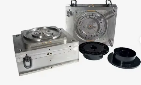
Injection Tooling refers to the high-precision, custom-built tool—most commonly called a mold (in the US) or tool (in Europe)—used in the injection molding process. It is the engineered system that gives molten plastic its shape, cooling it into a solid, functional part. The mold is the single most critical and expensive element in the injection molding workflow, representing a significant capital investment. Its design and construction directly determine the part's quality, dimensional accuracy, production efficiency, and ultimate cost.
2. Core Components of an Injection Mold
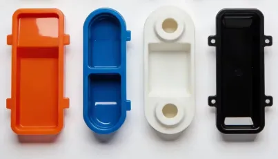
A standard injection mold is a complex assembly of several key components, typically categorized into the "A Side" and "B Side."
A-Side (Cavity Side / Fixed Half):
- This half is mounted on the fixed platen of the injection molding machine.
- It contains the sprue bushing, which receives the plastic from the machine nozzle.
- It usually houses the cavity—the impression that forms the external shape of the part.
B-Side (Core Side / Moving Half):
- This half is mounted on the moving platen of the machine.
- It usually houses the core—the feature that forms the internal shape of the part (e.g., the inside of a container).
- It contains the ejection system to push the finished part out of the mold.
Major Mold Components:
Component | Description & Function |
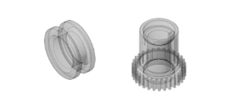
Core & Cavity | The master forms that create the part's geometry. The cavity forms the part's outer surface; the core forms the inner surface. |
Mold Base | A standardized frame that holds all the custom-machined components. It is typically purchased as a pre-made unit, saving cost and time. It includes plates like the "A" and "B" plates. |
Sprue Bushing | A hardened steel nozzle that connects the mold to the injection molding machine's nozzle, channeling molten plastic into the mold. |
Runner System | The network of channels that carries molten plastic from the sprue to the part cavities. |
Gates | The small, controlled entrance points from the runner into the part cavity. Gate design is critical for controlling plastic flow and part quality. |
Ejection System | The mechanism that pushes the cooled part off the core after the mold opens. It includes: |
Cooling (Temperature Control) System | A series of channels drilled through the mold plates and core/cavity blocks. Circulating water or oil through these channels controls the mold temperature, which is vital for cycle time and part quality. |
Venting | Very shallow channels (often only 0.01-0.03 mm deep) cut into the mold to allow trapped air to escape during injection, preventing defects like burns or short shots. |
Guide Pins/Bushings | Precision components that ensure the two halves of the mold align perfectly each time they close. |
3. Types of Injection Molds
Molds are classified based on their construction and the type of runner system they use.
A. By Runner System:
Type | Description | Pros & Cons |
Two-Plate Mold | The simplest and most common type. The runner system and parts are on the same parting line and are ejected together. | Pros: Simple design, lower cost. |
Three-Plate Mold | Features two parting lines. One opens to eject the runner system, and a second opens to eject the part. This allows the gate to be located away from the part's edge. | Pros: Automatic degating (runners separate from parts), gates can be placed at optimal locations. |
Hot Runner Mold | The runner system is heated and remains in a separate, heated manifold plate, so the plastic within it stays molten. No runner is ejected. | Pros: No scrap runners, faster cycle times, fully automated. |
B. By Production Volume & Material:
Type | Typical Material | Mold Life | Application |
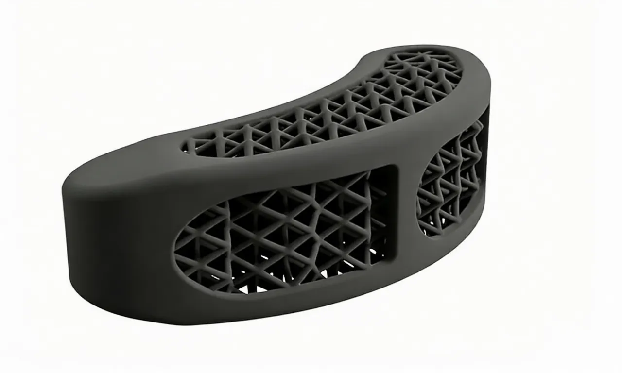
Prototype / Soft Tooling | Aluminum, mild steel, 3D printed metal/epoxy. | 1 - 10,000 shots | Low-volume production, prototyping, and market testing. Faster and cheaper to build. |
Production / Hard Tooling | Hardened Steel (e.g., P20, H13, S7). | 1,000,000+ shots | High-volume mass production. Highly wear-resistant but takes longer and costs more to build. |
4. Key Terminology in Mold Design & Manufacturing
Term | Definition & Context |
Parting Line (PL) | The visible line on the part where the two mold halves meet. Its location is a critical design decision. |
Draft Angle | A slight taper (typically 1°-3°) applied to walls parallel to the mold opening direction. Essential for easy part ejection. |
Shrinkage | The reduction in volume of the plastic as it cools. The mold must be built larger than the final part dimension to compensate for the specific plastic's shrinkage rate. |
Undercut | A feature on the part that prevents its direct ejection from the mold (e.g., a side hole, a hook). Requires special mold features. |
Lifter | A component that moves at an angle to release an undercut as the mold opens or during ejection. |
Slide (or Cam) | A component that moves perpendicular to the mold opening direction to form undercuts on the side of a part. |
Texture (EDM, Etching) | The process of applying a surface finish (e.g., leather grain, matte finish) to the mold cavity, often via Electrical Discharge Machining (EDM) or chemical etching. |
Mold Flow Analysis | Computer simulation software used during the design phase to predict how the plastic will fill the mold, allowing engineers to optimize gate location, cooling, and prevent defects. |
5. The Mold Lifecycle
- Design & Quoting: The part design is analyzed for manufacturability (DFM), and a mold is designed. A quote is provided based on complexity, size, and expected life.
- Mold Manufacturing (Mold Making): The mold is precision-machined using CNC milling, EDM, grinding, and polishing.
- Sampling (Trial Run): The finished mold is tested in an injection molding machine. Initial parts (T1 samples) are evaluated, and the mold is often adjusted (tweaked) to correct minor issues.
- Production: Once approved, the mold is used for mass production.
- Maintenance: Molds require regular cleaning, lubrication, and repair of wearing components to maintain part quality over their lifespan.
Conclusion
Injection tooling is a sophisticated field of engineering that blends precision machining, material science, and an intimate understanding of polymer behavior. The quality of the tool directly dictates the success of the entire production effort, making its design and construction a critical phase in bringing a plastic product to market
Hot Articles
Hot Tags
Stay Connected!


Manufacturing on Demand
Please fill in the following information to obtain plan details (information is confidential and not disclosed publicly), we will contact you within 24 hours, please keep your phone available!
Upload a 3D/2D model to see instant pricing, lead time, and DFM feedback.