


5-Axis Turning: Revolutionizing the Production of Aerospace Crankshafts


In the aerospace manufacturing industry, precision, reliability, and efficiency are not merely desirable attributes but absolute necessities. Every component that goes into an aircraft engine must meet stringent standards to ensure safe and consistent performance under extreme conditions—high temperatures, intense pressure, and constant mechanical stress. Among these critical components, the crankshaft stands out as a core part of the engine’s power transmission system, converting the reciprocating motion of pistons into rotational motion that drives the aircraft’s propellers or turbines. The complexity of its design, combined with the rigorous performance requirements, makes it a challenging component to manufacture. Traditional machining methods, such as 3-axis turning or milling, often struggle to meet the precision and efficiency demands of modern aerospace crankshaft production. This is where 5-axis turning technology emerges as a transformative solution, redefining the possibilities of crankshaft manufacturing with its unparalleled capabilities in handling complex geometries, reducing production time, and ensuring exceptional precision.
This article explores the application of 5-axis turning in the production of aerospace crankshafts, delving into the technical nuances of the process, its advantages over traditional machining methods, the key steps involved in manufacturing, and the critical factors that ensure the final product meets the strict standards of the aerospace industry. By focusing on this specific high-value product, we aim to provide a comprehensive understanding of how 5-axis turning is reshaping aerospace manufacturing and setting new benchmarks for precision and efficiency.
1. Overview of Aerospace Crankshafts: Design and Performance Requirements
Before delving into the role of 5-axis turning, it is essential to understand the unique characteristics of aerospace crankshafts and the challenges they pose to manufacturers. Unlike crankshafts used in automotive or industrial applications, aerospace crankshafts are designed to operate in extremely harsh environments, requiring exceptional strength, fatigue resistance, and dimensional accuracy. They are typically made from high-performance materials such as titanium alloys, nickel-based superalloys, or hardened steel, which offer superior mechanical properties but are also highly difficult to machine.
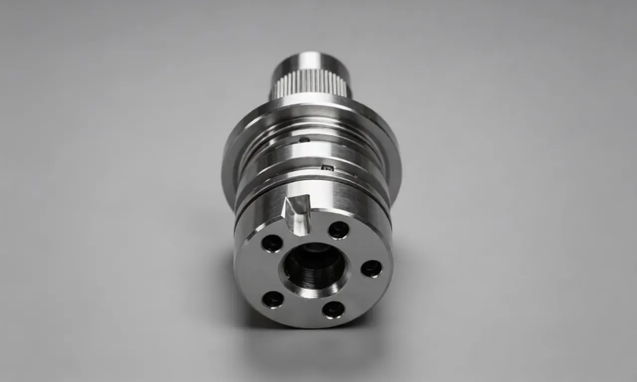
The structural complexity of aerospace crankshafts is another key challenge. A typical aerospace crankshaft consists of multiple main journals, connecting rod journals, crank arms, and counterweights, all arranged in a precise spatial configuration. The main journals are the cylindrical sections that rotate within the engine’s bearings, while the connecting rod journals (also known as crankpins) are offset from the main axis to convert linear piston motion into rotation. The crank arms connect the main journals to the connecting rod journals, and the counterweights are strategically placed to balance the crankshaft and reduce vibration during operation. This complex geometry requires precise machining of multiple surfaces, angles, and features, often with tight tolerances as low as ±0.005 mm.
In addition to dimensional precision, aerospace crankshafts must meet strict requirements for surface finish, fatigue strength, and dynamic balance. The surface roughness of critical contact areas, such as the journals, must be extremely low (typically Ra 0.2–0.8 μm) to minimize friction and wear within the engine. Fatigue strength is crucial because the crankshaft undergoes millions of cycles of alternating stress during its service life, and any imperfection or stress concentration could lead to catastrophic failure. Dynamic balance is also essential to reduce vibration, which can affect the engine’s performance and longevity. These requirements make the manufacturing process of aerospace crankshafts one of the most demanding in the aerospace industry.
Traditional machining methods, such as 3-axis turning and milling, have long been used for crankshaft production, but they have significant limitations when it comes to meeting the modern aerospace industry’s demands. 3-axis turning, for example, can only machine features along the X, Y, and Z linear axes, requiring multiple setups to machine complex angles and offset features. Each additional setup introduces the risk of repeat positioning errors, which can compromise the crankshaft’s dimensional accuracy and geometric tolerances. Moreover, 3-axis machining often requires extensive manual intervention, such as tool changes and workpiece repositioning, which increases production time and the potential for human error. As aerospace engine designs become more complex and performance requirements become more stringent, traditional machining methods are no longer sufficient. This is where 5-axis turning technology steps in, offering a solution that addresses these limitations and enables the efficient production of high-precision aerospace crankshafts.
2. Understanding 5-Axis Turning: Core Principles and Advantages
5-axis turning is an advanced CNC machining process that combines the capabilities of turning and milling, utilizing five axes of motion to machine complex parts in a single setup. Unlike 3-axis turning, which only uses three linear axes (X, Y, Z), 5-axis turning adds two rotational axes (typically A and B, or B and C), allowing the cutting tool or workpiece to rotate and tilt at various angles. This enables the tool to approach the workpiece from virtually any direction, eliminating the need for multiple setups and enabling the machining of complex geometries that would be impossible or impractical with traditional methods.
The core principle of 5-axis turning lies in its ability to synchronize the movement of all five axes, ensuring that the cutting tool maintains the optimal cutting angle and position throughout the machining process. This is made possible by advanced CNC control systems that use sophisticated algorithms to coordinate the motion of the linear and rotational axes. Many 5-axis turning machines also feature RTCP (Rotation Tool Center Point) functionality, which ensures that the tool’s center point remains fixed regardless of the machine’s rotation, maintaining consistent cutting conditions and improving precision.
When applied to aerospace crankshaft production, 5-axis turning offers a range of significant advantages over traditional machining methods, which are critical to meeting the industry’s strict requirements:
2.1 Single Setup Machining
One of the most significant advantages of 5-axis turning is its ability to machine all critical features of an aerospace crankshaft in a single setup. Traditional 3-axis machining requires multiple setups to machine offset journals, crank arms, and counterweights, each introducing the risk of repeat positioning errors. With 5-axis turning, the crankshaft is clamped once, and the machine’s rotational axes allow the tool to access all surfaces and features without repositioning the workpiece. This eliminates cumulative errors from multiple setups, significantly improving the crankshaft’s dimensional accuracy and geometric tolerances. For example, the coaxiality of the main journals and the parallelism of the connecting rod journals can be maintained within ±0.003 mm, which is essential for the crankshaft’s performance and longevity.
2.2 Enhanced Precision and Surface Quality
Aerospace crankshafts require exceptional precision and surface finish, and 5-axis turning delivers on both fronts. The elimination of multiple setups reduces the risk of errors, while the ability to maintain the optimal cutting angle throughout the process ensures consistent cutting conditions. The RTCP functionality of modern 5-axis machines ensures that the tool’s cutting edge is always in the ideal position, reducing tool vibration and improving surface finish. Additionally, 5-axis turning allows for the use of shorter cutting tools, which are more rigid and less prone to deflection, further enhancing precision. As a result, 5-axis turning can achieve surface roughness as low as Ra 0.1 μm on critical surfaces, meeting the strictest aerospace standards. The precise control over cutting parameters also reduces the risk of tool marks, burrs, and other surface imperfections that could compromise the crankshaft’s fatigue strength.
2.3 Improved Efficiency and Reduced Production Time
The single setup capability of 5-axis turning significantly reduces production time compared to traditional machining methods. By eliminating the need for multiple setups, tool changes, and workpiece repositioning, 5-axis turning can reduce the total machining time for an aerospace crankshaft by 30–50%. This is particularly important in the aerospace industry, where production volumes are often low but lead times are critical. Additionally, 5-axis turning combines turning and milling capabilities in a single machine, eliminating the need to transfer the workpiece between different machines for different operations. This not only saves time but also reduces the risk of damage to the workpiece during transfer. For example, a typical aerospace crankshaft that would take 18–24 hours to machine using 3-axis methods can be completed in 8–12 hours using 5-axis turning, significantly improving production efficiency.
2.4 Ability to Machine Complex Geometries
Aerospace crankshafts feature complex geometries, including offset journals, curved crank arms, and intricate counterweights, which are difficult or impossible to machine with 3-axis methods. 5-axis turning’s rotational axes allow the tool to access these complex features from multiple angles, enabling the machining of curved surfaces, inclined holes, and offset features with high precision. For example, the crank arms of an aerospace crankshaft often have complex curved profiles to reduce weight while maintaining strength, and 5-axis turning can machine these profiles in a single pass, ensuring consistency and precision. The ability to machine complex geometries also allows for more optimized crankshaft designs, reducing weight and improving fuel efficiency without compromising strength or performance.
2.5 Reduced Tool Wear and Longer Tool Life
The optimal cutting angles maintained by 5-axis turning reduce tool wear and extend tool life, which is critical when machining high-performance materials such as titanium alloys and nickel-based superalloys. These materials are highly abrasive and can quickly wear down cutting tools, leading to increased tool costs and production downtime. By maintaining the ideal cutting angle, 5-axis turning reduces the cutting forces and heat generated during machining, minimizing tool wear. Additionally, the use of shorter, more rigid tools reduces tool deflection, further reducing wear and improving tool life. This not only reduces tool costs but also improves production consistency, as worn tools are less likely to produce defective parts.
3. The 5-Axis Turning Process for Aerospace Crankshaft Production
The production of aerospace crankshafts using 5-axis turning is a complex, multi-step process that requires careful planning, precise setup, and advanced control systems. Each step is critical to ensuring the final product meets the strict standards of the aerospace industry. Below is a detailed overview of the key steps involved in the 5-axis turning process for aerospace crankshafts:
3.1 Material Selection and Preparation
The first step in crankshaft production is the selection of the appropriate material. As mentioned earlier, aerospace crankshafts are typically made from high-performance materials such as titanium alloys (e.g., Ti-6Al-4V), nickel-based superalloys (e.g., Inconel 718), or hardened steel (e.g., AISI 4340). These materials offer superior strength, fatigue resistance, and high-temperature performance, making them ideal for aerospace applications. However, they are also highly difficult to machine, requiring specialized cutting tools and machining parameters.
Once the material is selected, it is prepared for machining. The raw material is typically supplied as a forged or cast blank, which is then subjected to heat treatment to improve its mechanical properties. Heat treatment processes such as annealing, quenching, and tempering are used to reduce internal stresses, improve hardness, and enhance fatigue strength. After heat treatment, the blank is inspected to ensure it meets the required material specifications, including chemical composition, hardness, and microstructure. The blank is then machined to a rough shape, removing excess material and preparing it for the 5-axis turning process. This rough machining step is often performed using 3-axis milling or turning machines to reduce the amount of material that needs to be removed during the more precise 5-axis turning process.
3.2 CNC Programming and Toolpath Optimization
CNC programming is a critical step in 5-axis turning, as it determines the tool’s path, cutting parameters, and machine movements. The programming process begins with the design of the crankshaft using CAD (Computer-Aided Design) software, which creates a 3D model of the crankshaft with all its features and dimensions. The CAD model is then imported into CAM (Computer-Aided Manufacturing) software, which generates the toolpath for the 5-axis turning machine.
The CAM software uses advanced algorithms to optimize the toolpath, ensuring that the tool moves efficiently and maintains the optimal cutting angle throughout the process. Key considerations in toolpath optimization include minimizing tool travel time, reducing tool vibration, and ensuring that all features are machined with the required precision. For aerospace crankshafts, the toolpath must be carefully designed to machine the main journals, connecting rod journals, crank arms, and counterweights in a single setup. The CAM software also accounts for the machine’s capabilities, including the range of motion of the linear and rotational axes, to avoid collisions between the tool, workpiece, and machine components.
Cutting parameters, such as spindle speed, feed rate, and depth of cut, are also determined during the programming process. These parameters are optimized based on the material being machined, the type of cutting tool, and the desired surface finish and precision. For example, when machining titanium alloys, lower feed rates and higher spindle speeds are typically used to reduce heat generation and tool wear. The programming process also includes tool selection, with specialized tools such as carbide or cubic boron nitride (CBN) tools used for machining high-performance materials.
3.3 Workpiece Setup and Clamping
Proper workpiece setup and clamping are essential to ensuring the precision of the 5-axis turning process. The crankshaft blank is clamped in a chuck or fixture that is mounted on the machine’s rotational axis (typically the C-axis). The clamping system must be rigid enough to withstand the cutting forces generated during machining, while also ensuring that the workpiece is positioned accurately relative to the machine’s axes. For aerospace crankshafts, specialized fixtures are often used to ensure that the blank is aligned correctly and that the main axis of the crankshaft is coincident with the machine’s rotational axis.
Zero-point positioning systems are often used to ensure precise and repeatable positioning of the workpiece. These systems use precision locating pins and clamping devices to quickly and accurately position the workpiece in the fixture, reducing setup time and ensuring consistent positioning. The clamping force must be carefully controlled to avoid damaging the workpiece or causing deformation, which could compromise the crankshaft’s precision. For thin-walled or delicate features, lower clamping forces are used, often with additional support to prevent deformation during machining.
3.4 Rough Machining
The rough machining step is designed to remove the majority of the excess material from the blank, bringing it close to the final shape of the crankshaft. During rough machining, the 5-axis turning machine uses high feed rates and large depths of cut to quickly remove material, while maintaining the overall geometry of the crankshaft. The rough machining process typically involves turning the main journals and connecting rod journals, machining the crank arms, and roughing the counterweights. The goal of rough machining is to minimize the amount of material that needs to be removed during the finishing step, while also ensuring that the workpiece remains stable and free from deformation.
During rough machining, the machine’s rotational axes (A and B, or B and C) are used to position the workpiece at the optimal angle for each cut. The cutting tool moves along the linear axes (X, Y, Z) to remove material, while the rotational axes adjust the workpiece’s orientation to allow access to all features. The rough machining step is typically performed using carbide inserts, which are designed to withstand the high cutting forces and heat generated during the process. Coolant is also used extensively during rough machining to reduce heat, lubricate the cutting tool, and flush away chips, preventing chip buildup and tool wear.
3.5 Finishing Machining
After rough machining, the crankshaft undergoes finishing machining to achieve the final dimensions, surface finish, and precision required. Finishing machining is performed at lower feed rates and smaller depths of cut, with a focus on maintaining tight tolerances and improving surface quality. The finishing step involves machining the main journals, connecting rod journals, and other critical features to their final dimensions, as well as machining the curved profiles of the crank arms and counterweights.
During finishing machining, the 5-axis turning machine’s RTCP functionality is critical to maintaining the optimal cutting angle and ensuring consistent surface finish. The toolpath is optimized to minimize tool marks and burrs, with multiple passes used to achieve the desired surface roughness. For critical surfaces such as the journals, a final polishing step may be performed to further improve surface finish and reduce friction. The finishing step also includes machining any holes, slots, or other features required for the crankshaft’s assembly into the engine.
3.6 Quality Control and Inspection
Quality control is a critical step in the production of aerospace crankshafts, as even the smallest imperfection can lead to catastrophic failure. After finishing machining, the crankshaft undergoes a series of rigorous inspections to ensure it meets all dimensional, geometric, and surface finish requirements. Advanced inspection tools are used to measure the crankshaft’s dimensions, including the diameter of the main and connecting rod journals, the distance between journals, and the parallelism and coaxiality of critical features.
Coordinate Measuring Machines (CMMs) are commonly used to inspect the crankshaft’s geometry, providing precise measurements of all features in three dimensions. CMMs use a probe to scan the crankshaft’s surface, comparing the measured dimensions to the CAD model to ensure compliance with tolerances. Other inspection tools include surface roughness testers, which measure the surface finish of critical areas, and dynamic balance testers, which ensure the crankshaft is properly balanced to reduce vibration during operation.
In addition to dimensional and geometric inspections, the crankshaft may also undergo non-destructive testing (NDT) to detect internal defects such as cracks, inclusions, or voids. NDT methods such as ultrasonic testing, magnetic particle testing, or X-ray inspection are used to ensure the crankshaft’s structural integrity. Any crankshaft that fails to meet the inspection standards is either reworked or discarded, ensuring only high-quality components are used in aerospace engines.
4. Key Challenges and Solutions in 5-Axis Turning of Aerospace Crankshafts
While 5-axis turning offers significant advantages for aerospace crankshaft production, it also presents a number of challenges that must be addressed to ensure successful implementation. These challenges include machining high-performance materials, maintaining precision during complex machining operations, and managing the complexity of CNC programming. Below are the key challenges and their corresponding solutions:
4.1 Machining High-Performance Materials
Aerospace crankshafts are typically made from titanium alloys, nickel-based superalloys, or hardened steel, which are highly difficult to machine. These materials have high hardness, strength, and toughness, leading to high cutting forces, heat generation, and tool wear. Machining these materials requires specialized cutting tools, cutting parameters, and cooling systems.
Solution: The use of advanced cutting tools, such as carbide, CBN, or diamond-coated tools, which offer superior hardness and wear resistance. These tools are designed to withstand the high cutting forces and heat generated during machining. Additionally, optimized cutting parameters, such as low feed rates, high spindle speeds, and small depths of cut, are used to reduce heat generation and tool wear. Coolant systems, including high-pressure coolant (HPC) systems, are also used to deliver coolant directly to the cutting zone, reducing heat and flushing away chips. HPC systems can deliver coolant at pressures of up to 1000 bar, ensuring effective cooling and chip evacuation, which is critical when machining high-performance materials.
4.2 Maintaining Precision During Complex Machining
The complex geometry of aerospace crankshafts, combined with the need for tight tolerances, makes maintaining precision during 5-axis turning a significant challenge. Factors such as tool vibration, workpiece deformation, and machine errors can all compromise the crankshaft’s precision.
Solution: The use of rigid machine designs and high-precision components, such as linear guides and ball screws, to minimize machine vibration and errors. Additionally, the use of shorter, more rigid cutting tools reduces tool deflection, improving precision. Workpiece deformation is minimized by using proper clamping techniques and support fixtures, as well as by optimizing cutting parameters to reduce cutting forces. Advanced CNC control systems with real-time feedback mechanisms are also used to monitor and correct for any deviations during machining, ensuring consistent precision.
4.3 CNC Programming Complexity
5-axis turning requires complex CNC programming, as the toolpath must coordinate the movement of five axes simultaneously. Programming errors can lead to collisions between the tool, workpiece, and machine components, as well as defective parts.
Solution: The use of advanced CAM software with 5-axis programming capabilities, which simplifies the programming process and reduces the risk of errors. CAM software includes features such as collision detection, which identifies potential collisions before the program is run, and toolpath simulation, which allows programmers to visualize the machining process and make adjustments as needed. Additionally, training and certification for CNC programmers are essential to ensure they have the skills and knowledge to program 5-axis turning machines effectively. Many manufacturers also use post-processors that are specifically designed for their 5-axis machines, ensuring that the CAM-generated toolpath is compatible with the machine’s control system.
4.4 Tool Management
The use of multiple cutting tools during 5-axis turning, combined with the high tool wear associated with machining high-performance materials, makes tool management a critical challenge. Tool breakage or wear can lead to production downtime and defective parts.
Solution: The use of tool management systems that monitor tool wear and tool life, providing real-time feedback to operators. These systems can track the number of cuts a tool has made, the cutting time, and the wear level, alerting operators when a tool needs to be replaced. Additionally, tool presetters are used to accurately measure the length and diameter of cutting tools before they are installed in the machine, ensuring that the toolpath is accurate and reducing the risk of errors. Many 5-axis turning machines also feature automatic tool changers, which reduce tool change time and improve production efficiency.
5. Case Study: 5-Axis Turning in Aerospace Crankshaft Production
To illustrate the practical application of 5-axis turning in aerospace crankshaft production, let’s consider a case study of a leading aerospace manufacturer that adopted 5-axis turning to produce crankshafts for a next-generation jet engine. The manufacturer was facing challenges with their traditional 3-axis machining process, including long production times, high defect rates, and difficulty meeting the strict precision requirements for the new crankshaft design.
The crankshaft in question was made from Inconel 718, a nickel-based superalloy known for its high strength and high-temperature performance. The crankshaft featured multiple offset connecting rod journals, curved crank arms, and intricate counterweights, with tolerances as low as ±0.003 mm and a surface roughness requirement of Ra 0.2 μm. The traditional 3-axis machining process required 6 setups, took 22 hours to complete, and had a defect rate of 12% due to repeat positioning errors and tool wear.
The manufacturer invested in a 5-axis turning center with RTCP functionality, advanced CAM software, and a high-pressure coolant system. They also trained their CNC programmers and operators on 5-axis machining techniques. The new 5-axis process allowed the crankshaft to be machined in a single setup, reducing the production time to 10 hours—a 55% reduction. The elimination of multiple setups reduced the defect rate to less than 2%, as repeat positioning errors were eliminated. The RTCP functionality and optimized toolpath improved the surface finish to Ra 0.15 μm, exceeding the required standard. Additionally, the use of advanced cutting tools and high-pressure coolant reduced tool wear by 40%, lowering tool costs and production downtime.
The success of this case study demonstrates the transformative impact of 5-axis turning on aerospace crankshaft production. By adopting 5-axis technology, the manufacturer was able to improve precision, reduce production time, lower defect rates, and reduce costs—all critical factors in the competitive aerospace industry.
6. Future Trends in 5-Axis Turning for Aerospace Crankshaft Production
As the aerospace industry continues to evolve, 5-axis turning technology is also advancing to meet the growing demands for higher precision, efficiency, and sustainability. Below are some of the key future trends in 5-axis turning for aerospace crankshaft production:
6.1 Integration of Artificial Intelligence (AI) and Machine Learning (ML)
AI and ML are being integrated into 5-axis turning machines to optimize the machining process in real time. AI-powered systems can monitor cutting parameters, tool wear, and machine performance, making adjustments to improve precision and efficiency. For example, AI algorithms can predict tool wear and adjust cutting parameters to extend tool life, or detect deviations in the machining process and correct them before defects occur. This integration will further improve the consistency and reliability of 5-axis turning, reducing the need for human intervention and improving production efficiency.
6.2 Automation and Robotics
Automation and robotics are becoming increasingly important in aerospace manufacturing, and 5-axis turning is no exception. Automated loading and unloading systems, robotic arms, and collaborative robots (cobots) are being used to streamline the production process, reducing human error and increasing production efficiency. For example, cobots can load and unload workpieces into the 5-axis turning machine, freeing up operators to focus on more complex tasks such as programming and quality control. Automation also enables lights-out manufacturing, where the machine operates 24/7 without human supervision, further increasing production capacity.
6.3 Advanced Materials and Machining Techniques
The development of new advanced materials, such as composite materials and additive-manufactured blanks, is driving the evolution of 5-axis turning techniques. Composite materials, which are lightweight and strong, are increasingly being used in aerospace crankshafts, but they require specialized machining techniques to avoid damage. 5-axis turning machines are being adapted to machine these materials, with specialized tools and cutting parameters. Additionally, additive manufacturing (AM) is being used to produce crankshaft blanks with near-net shapes, reducing the amount of material that needs to be removed during machining. 5-axis turning is then used to finish the AM blanks, ensuring the required precision and surface finish.
6.4 Sustainability and Energy Efficiency
Sustainability is a growing focus in the aerospace industry, and 5-axis turning is being optimized to reduce energy consumption and waste. New 5-axis turning machines are being designed with energy-efficient motors and components, reducing power consumption. Additionally, optimized toolpaths and cutting parameters reduce material waste and tool consumption, making the process more sustainable. The use of coolant recycling systems also reduces water consumption and environmental impact.
7. Conclusion
5-axis turning technology has revolutionized the production of aerospace crankshafts, offering unparalleled precision, efficiency, and flexibility. By eliminating multiple setups, reducing errors, and enabling the machining of complex geometries, 5-axis turning has become the preferred method for manufacturing high-precision, high-performance crankshafts that meet the strict standards of the aerospace industry. The process’s ability to machine high-performance materials, improve surface quality, and reduce production time has made it a critical technology for aerospace manufacturers looking to stay competitive in a rapidly evolving industry.
While 5-axis turning presents challenges, such as machining complex materials and programming complexity, these challenges can be addressed through the use of advanced tools, software, and training. As technology continues to advance, the integration of AI, automation, and advanced materials will further enhance the capabilities of 5-axis turning, making it even more efficient and precise.
In conclusion, 5-axis turning is not just a machining process—it is a transformative technology that is shaping the future of aerospace manufacturing. By enabling the production of more precise, efficient, and reliable crankshafts, 5-axis turning is helping to drive innovation in the aerospace industry, ensuring that aircraft engines are safer, more efficient, and more sustainable than ever before. As the demand for high-performance aerospace components continues to grow, 5-axis turning will remain a critical tool for manufacturers seeking to meet these demands and stay at the forefront of the industry.
Hot Articles
Hot Tags
Stay Connected!


Manufacturing on Demand
Please fill in the following information to obtain plan details (information is confidential and not disclosed publicly), we will contact you within 24 hours, please keep your phone available!
Upload a 3D/2D model to see instant pricing, lead time, and DFM feedback.