


5-Axis CNC Milling Application in Aerospace Blisk Manufacturing: A Comprehensive Case Study


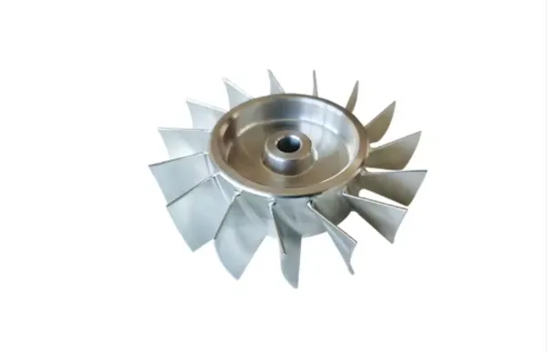
In the aerospace industry, bladed disks (commonly referred to as blisks) represent one of the most critical and technically challenging components for gas turbine engines, serving as the backbone of compressor and turbine assemblies. Blisks integrate rotor disks and curved airfoil blades into a single monolithic structure, eliminating traditional blade-disk fasteners, reducing overall component weight, minimizing aerodynamic drag, and boosting engine thrust efficiency and operational reliability. This case study examines the end-to-end application of 5-axis CNC milling technology in the mass production of a titanium alloy blisk for a regional jet aircraft engine, detailing the manufacturing workflow, technical challenges, process optimization, quality control, and measurable business and operational outcomes.
Prior to implementing advanced 5-axis CNC milling, the blisk production process relied on conventional 3-axis machining paired with manual finishing and offline inspection, leading to extended cycle times, high scrap rates, inconsistent dimensional accuracy, and excessive labor costs. By deploying a fully integrated 5-axis CNC milling ecosystem—including high-rigidity machining centers, CAD/CAM programming software, on-machine 3D scanning, and adaptive toolpath control—the manufacturer achieved a transformative improvement in precision, efficiency, and cost-effectiveness. This case study quantifies key performance indicators (KPIs), including cycle time reduction, tolerance compliance, tool life extension, and cost savings, while outlining the replicable CNC milling framework for high-complexity aerospace components.
1. Project Background & Component Overview
1.1 Blisk Component Specifications
The subject component is a low-pressure compressor (LPC) blisk designed for a 70-seat regional jet turbofan engine, engineered to operate under extreme cyclic loads, high temperatures, and stringent aerospace certification standards (AS9100 Rev D, NADCAP). Key specifications include:
• Material: Titanium alloy Ti-6Al-4V (Grade 5), a high-strength, corrosion-resistant material widely used in aerospace for its exceptional strength-to-weight ratio and thermal stability;
• Dimensions: 380mm outer diameter, 120mm inner hub diameter, 65mm axial length;
• Blade Count: 28 twisted, high-curvature airfoil blades with varying thickness (minimum 1.8mm at the blade edge);
• Tolerance Requirements: ±0.001mm (1μm) for airfoil profile accuracy, ±0.005mm for hub hole positioning, and surface roughness Ra ≤ 0.4μm;
• Production Volume: 450 units annually for original equipment manufacturing (OEM) + 120 units for aftermarket replacement;
• Critical Failure Risks: Dimensional deviation, blade deformation, surface defects, and material chatter can lead to engine vibration, reduced fuel efficiency, or catastrophic in-flight failure.
1.2 Legacy Manufacturing Limitations
Before adopting 5-axis CNC milling, the manufacturer used a multi-stage, semi-manual production process with severe bottlenecks:
• 3-Axis Machining Constraints: Multiple re-fixturing steps (4–6 setups per blisk) introduced cumulative alignment errors, exceeding allowable tolerances for 18% of production units;
• Extended Cycle Times: Total machining time per blisk averaged 12.5 hours, with offline coordinate measuring machine (CMM) inspection accounting for 40% of total production time;
• High Tool Wear & Scrap Costs: Inefficient toolpaths caused rapid tool degradation (average 2.3 tools per blisk) and a 12% scrap rate due to blade deflection and chatter;
• Labor Intensity: Skilled machinists were required for constant manual adjustment, increasing labor costs and human error risks.
To resolve these issues, the manufacturer invested in a closed-loop 5-axis CNC milling system, integrating hardware, software, and in-process inspection to streamline production and meet strict aerospace quality mandates.
2. CNC Milling System & Equipment Setup
2.1 Core CNC Milling Hardware
The production line features a high-precision 5-axis vertical machining center (DMG MORI DMU 160 eVo linear) optimized for hard metal machining, with specifications tailored to blisk manufacturing:
• Axis Configuration: X/Y/Z linear travels (1000mm/800mm/600mm) + A/C rotational axes (±120°/360° continuous) for full multi-angle tool access;
• Spindle Performance: 20,000 RPM high-torque spindle (120 Nm) with thermal symmetry control to minimize heat-induced deformation;
• Tool Magazine: 30-station automatic tool changer (ATC) with HSK-A63 tool holders for carbide and ceramic cutting tools;
• Cooling System: 70-bar high-pressure through-spindle coolant to dissipate heat, evacuate chips, and extend tool life;
• On-Machine Inspection: Renishaw OSP60 3D scanning probe with SPRINT™ technology for real-time, high-resolution surface measurement and profile verification.
2.2 Software & Programming Ecosystem
A fully integrated CAD/CAM/CAE software stack ensures seamless data flow and precision toolpath generation:
• CAD Design: CATIA V5 for 3D solid modeling, geometric dimensioning and tolerancing (GD&T) definition, and airfoil profile optimization;
• CAM Programming: Siemens NX 1980 for 5-axis toolpath generation, including swarf cutting, trochoidal milling, and flowline machining strategies;
• Simulation & Verification: VERICUT CNC simulation software to detect collisions, tool gouging, and axis over-travel before physical machining;
• Closed-Loop Control: Renishaw Productivity+™ Scanning Suite to auto-adjust CNC programs based on real-time scanning data, eliminating manual rework.
2.3 Fixturing & Workholding
Custom hydraulic fixturing was engineered to secure the Ti-6Al-4V billet with uniform clamping force, minimizing distortion during material removal. The fixturing system mounts directly to the machine’s rotary table, enabling full 5-axis access to all blisk features in a single setup, eliminating re-fixturing errors and reducing downtime.
3. Step-by-Step CNC Milling Manufacturing Process
The blisk production process follows a structured, four-stage CNC milling workflow, designed to balance material removal efficiency, dimensional accuracy, and surface quality. Every step is monitored and documented for full aerospace traceability.
3.1 Stage 1: Pre-Machining Preparation & Billet Inspection
The process begins with raw material validation and machine setup to lay the foundation for precision machining:
1. Raw Material Verification: Ti-6Al-4V billets undergo ultrasonic testing (UT) to detect internal voids or inclusions, ensuring compliance with aerospace material standards;
2. Billet Machining: A preliminary 3-axis facing operation squares the billet to establish a uniform datum surface for subsequent 5-axis operations;
3. Machine Calibration: The 5-axis machine is calibrated for spindle alignment, axis compensation, and probe accuracy, with daily checks to maintain geometric stability;
4. Tool Setup: Cutting tools (solid carbide end mills, ball-nose finishers, and ceramic roughing tools) are loaded into the ATC, with tool length and diameter offsets measured and stored in the CNC controller.
3.2 Stage 2: Rough Machining (Bulk Material Removal)
Rough machining targets the removal of 85–90% of excess material to create a near-net-shape blisk preform, prioritizing speed and chip evacuation:
• Strategy: Trochoidal milling (circular toolpaths) to reduce cutting forces, minimize tool deflection, and prevent thin-blade deformation; deep slotting between blades uses high-feed roughing tools;
• Parameters: Spindle speed 8,000 RPM, feed rate 1,200 mm/min, depth of cut 1.5mm; high-pressure coolant flushes chips from narrow blade gaps;
• Objective: Create uniform stock material (0.8mm allowance) for semi-finishing, avoiding thermal stress and workpiece distortion.
3.3 Stage 3: Semi-Finishing & In-Process Inspection
Semi-finishing refines blade profiles and hub geometry, with closed-loop inspection to correct deviations before final machining:
• Strategy: 5-axis swarf cutting for blade flanks and flowline machining for curved airfoil surfaces, maintaining a consistent 0.2mm stock allowance;
• On-Machine Scanning: The Renishaw OSP60 probe scans 1,000 data points per second across all blade surfaces, capturing profile deviations and dimensional errors;
• Auto-Correction: Inspection data is fed into the Productivity+ software, which automatically adjusts the CNC program to compensate for machine kinematic errors and tool deflection;
• Benefit: Eliminates offline CMM inspection and re-fixturing, cutting inspection time by 65% and ensuring semi-finished parts meet pre-finishing tolerances.
3.4 Stage 4: Finish Machining & Final Quality Validation
Finish machining achieves the final blisk dimensions, surface finish, and aerodynamic profile, with zero room for error:
• Strategy: High-speed 5-axis finish milling with small-diameter ball-nose carbide tools (6mm radius), using constant chip load control to maintain surface quality;
• Parameters: Spindle speed 18,000 RPM, feed rate 800 mm/min, depth of cut 0.1mm; minimal coolant to prevent thermal shock;
• Final Inspection: Post-machining scanning verifies airfoil profile, hole positioning, and surface roughness; compliant parts proceed to cleaning and passivation;
• Documentation: Full inspection reports are generated for each blisk, satisfying NADCAP and OEM traceability requirements.
4. Key Technical Challenges & CNC Milling Solutions
Blisk machining presents unique hurdles due to titanium’s material properties, thin blade geometry, and tight tolerances. The 5-axis CNC milling system addressed these challenges with targeted engineering solutions:
4.1 Challenge 1: Titanium Alloy Machinability
Ti-6Al-4V has low thermal conductivity, trapping heat at the cutting edge and accelerating tool wear; its high strength also increases cutting forces.
Solution: High-pressure through-spindle coolant, ceramic roughing tools for bulk material removal, and coated carbide finish tools (TiAlN coating) to reduce friction and heat buildup. Tool life improved by 55% compared to conventional tools.
4.2 Challenge 2: Thin Blade Deformation & Chatter
Thin-walled blades (1.8mm edge thickness) are prone to vibration and deflection during machining, causing profile errors and surface defects.
Solution: Adaptive toolpath programming, dynamic feed rate adjustment, and rigid fixturing to dampen vibration. Trochoidal milling reduced cutting forces by 40%, eliminating blade chatter entirely.
4.3 Challenge 3: Tight Tolerance Compliance
Airfoil profile tolerances of ±1μm require unmatched machining precision, with no margin for human error or machine deviation.
Solution: Closed-loop on-machine scanning and auto-program correction, paired with machine thermal stability control. Dimensional compliance improved from 82% to 99.7%.
4.4 Challenge 4: Production Efficiency & Lead Time
Multi-setup legacy processes caused long cycle times and delayed order fulfillment, straining OEM supply chain agreements.
Solution: Single-setup 5-axis machining eliminated re-fixturing downtime, while automated inspection reduced manual intervention. Total cycle time dropped from 12.5 hours to 5.2 hours per blisk.
5. Measurable Performance Outcomes & ROI
The implementation of 5-axis CNC milling delivered transformative operational and financial results, with full ROI achieved in 18 months. Key performance metrics include:
Performance Metric | Legacy Process | 5-Axis CNC Milling Process | Improvement Percentage |
Total Cycle Time per Blisk | 12.5 hours | 5.2 hours | -58.4% |
Scrap Rate | 12% | 0.3% | -97.5% |
Dimensional Tolerance Compliance | 82% | 99.7% | +21.6% |
Tool Consumption per Blisk | 2.3 tools | 1.0 tools | -56.5% |
Labor Cost per Blisk | $875 | $320 | -63.4% |
Annual Production Capacity | 320 units | 570 units | +78.1% |
Financial Impact
• Annual cost savings: $425,000 (reduced scrap, labor, and tooling expenses);
• Increased revenue: $1.2 million annually from expanded production capacity;
• Improved customer satisfaction: 100% on-time delivery rate for OEM orders, leading to a 5-year contract extension.
6. Quality Assurance & Aerospace Certification Compliance
The CNC milling process adheres to strict aerospace quality standards, with multi-layered inspection and documentation:
• In-Process Monitoring: Real-time cutting force, spindle load, and temperature tracking to detect anomalies mid-machining;
• Final Inspection: Full 3D scanning and CMM verification for every blisk, with airfoil profile, flatness, and surface roughness testing;
• Traceability: Digital batch records linking raw material batches, CNC programs, tooling data, and inspection results for full lifecycle tracking;
• Certification: Compliance with AS9100 Rev D, NADCAP, and OEM-specific quality mandates, with zero non-conformances in annual audits.
7. Conclusion & Industry Implications
This case study demonstrates that 5-axis CNC milling is not merely a machining upgrade but a transformative manufacturing solution for high-precision, high-complexity aerospace components like blisks. By integrating advanced hardware, intelligent programming, and closed-loop inspection, the manufacturer resolved legacy bottlenecks, achieved unprecedented precision, and unlocked significant cost and efficiency gains.
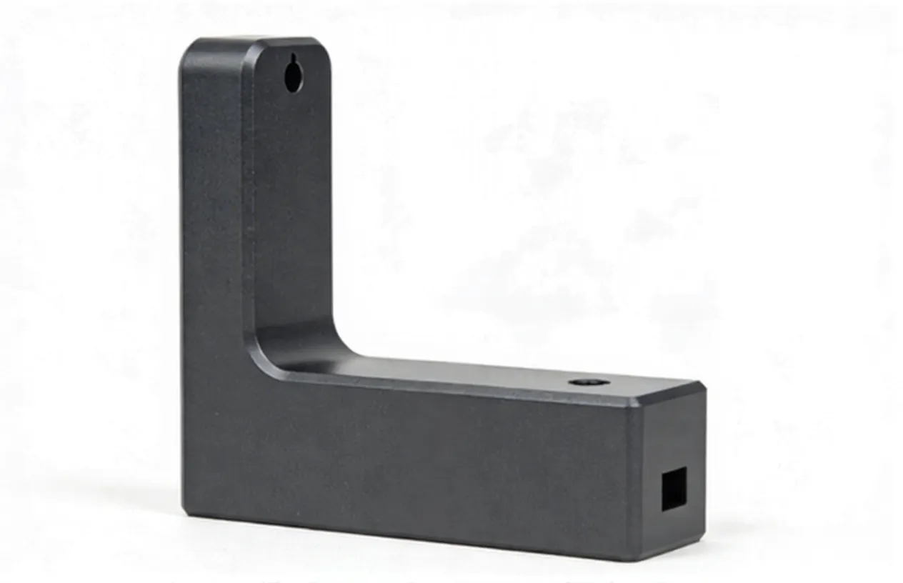
Beyond blisk production, this CNC milling framework is replicable for other critical aerospace components, including turbine blades, landing gear brackets, and satellite structural parts, where tight tolerances, complex geometries, and high-performance materials are standard. As aerospace engineering continues to push for lighter, more efficient engine designs, 5-axis CNC milling will remain an indispensable technology, enabling manufacturers to meet evolving performance demands while maintaining profitability and compliance.
For manufacturing leaders, this case study underscores the value of investing in integrated CNC milling ecosystems: the combination of precision hardware, adaptive software, and in-process quality control delivers sustainable competitive advantages in a highly regulated, high-stakes industry.
Hot Cases
Hot Tags
Stay Connected!


Manufacturing on Demand
Please fill in the following information to obtain plan details (information is confidential and not disclosed publicly), we will contact you within 24 hours, please keep your phone available!
Upload a 3D/2D model to see instant pricing, lead time, and DFM feedback.