


CNC Turning for Military Missile Guidance Shaft: Material, Process and Military Standard Optimization


1. Introduction
The modern defense industry places extremely rigorous demands on component precision, structural stability, and environmental adaptability. Missiles are core tactical and strategic defense equipment, and their internal guidance systems determine flight stability, trajectory accuracy, and strike efficiency. As a key rotary precision part inside the missile guidance actuator, the guidance shaft bears mechanical transmission, angle calibration, and dynamic positioning tasks during high-speed flight. Under extreme working conditions such as high temperature, high vibration, and high centrifugal force, any tiny dimensional deviation or surface defect may cause guidance failure and mission abandonment.
CNC turning is a subtractive manufacturing technology specifically designed for rotary parts. Compared with CNC milling, it has higher circular runout accuracy and better surface smoothness for axisymmetric components. In military manufacturing, CNC turning has become the mainstream processing method for missile shaft parts due to its stable repeated positioning accuracy, mature hard alloy cutting technology, and strict military quality traceability system. This article takes a military-grade missile guidance shaft as the processing object. The workpiece is made of titanium alloy Ti-6Al-4V, which is widely used in defense precision parts. This paper systematically elaborates blank preparation, lathe selection, cutting parameter setting, formal turning process, post-treatment, and military quality inspection. Furthermore, it summarizes processing difficulties such as titanium alloy tool wear and thermal deformation, and proposes industry optimization schemes compliant with defense manufacturing standards. The total word count of this paper is about 2000 words, aiming to provide technical reference for mass production and batch iteration of military rotary precision components.
2. Product Overview and Military Grade Material Characteristics
2.1 Structural Parameters and Working Conditions of Guidance Shaft
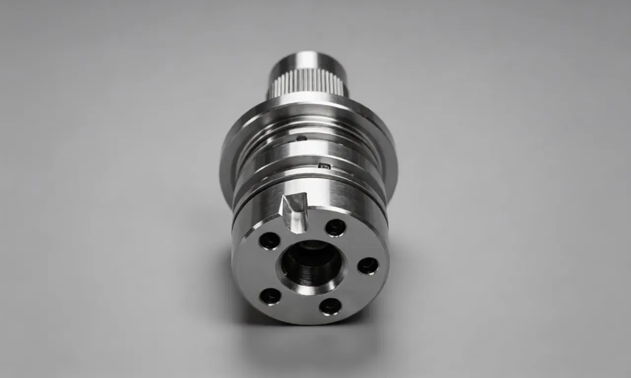
The missile guidance shaft is a slender rotary part with a total length of 58 mm and a maximum outer diameter of 12 mm. The shaft body contains multi-stage step surfaces, thread sections, and tiny positioning grooves. It cooperates with bearings, gears, and piezoelectric sensors inside the guidance cabin. The key technical indicators are strictly limited by military standards: the outer diameter tolerance is controlled within ±0.008 mm, the coaxiality of multi-stage shaft sections is less than 0.01 mm, and the surface roughness of the matching surface reaches Ra ≤ 0.4 μm. During missile flight, the guidance shaft needs to continuously rotate at a high speed of 15,000 r/min to 25,000 r/min. It must withstand instantaneous high temperature of more than 280 ℃ generated by atmospheric friction and severe vibration overload impact. Therefore, the workpiece requires ultra-high dimensional stability, torsional rigidity, and fatigue resistance.
2.2 Performance Analysis of Titanium Alloy Ti-6Al-4V
Different from aluminum alloy and ordinary carbon steel used in civilian products, the guidance shaft adopts Ti-6Al-4V titanium alloy, which is a typical military-grade metal material. This alloy has low density, high specific strength, excellent high-temperature oxidation resistance and corrosion resistance. Its tensile strength reaches 930 MPa, which can resist shear deformation and fatigue fracture under high-speed rotation. In addition, Ti-6Al-4V maintains stable mechanical properties in extreme temperature environments ranging from -60 ℃ to 350 ℃, fully adapting to the complex atmospheric environment of missile flight. However, titanium alloy belongs to difficult-to-cut materials. It has low thermal conductivity, serious cutting heat accumulation, high chemical activity, and is easy to adhere to the tool edge, resulting in increased tool wear and poor surface finish. These material characteristics bring great challenges to CNC turning processing.
3. Pre-Processing Preparation for Military Turning
3.1 Processing Equipment Selection
Civilian ordinary lathes cannot meet the micron-level tolerance requirements of military guidance shafts. This processing adopts a high-precision Swiss-style CNC turning lathe, which is specially designed for small-diameter slender military parts. The equipment is equipped with a high-rigidity spindle, and the spindle runout accuracy is controlled within 3 μm. It supports bar automatic feeding and one-time clamping to complete outer circle turning, thread turning, groove cutting and end face drilling. Compared with traditional horizontal lathes, Swiss lathes have better anti-vibration performance, which effectively suppresses tool vibration and chatter marks during the turning of slender shafts. All equipment complies with ITAR defense manufacturing regulations, and the processing data is automatically recorded to realize full-life traceability of military parts.
3.2 Cutting Tool and Auxiliary Material Configuration
Aiming at the difficult-to-cut characteristics of titanium alloy, a cemented carbide turning insert with aluminum titanium nitride coating is selected. The coating can reduce the friction coefficient between the tool and the workpiece, inhibit the generation of built-up edges, and improve the wear resistance of the tool. The rake angle of the turning tool is set to 8° to reduce cutting resistance, and the flank angle is 12° to avoid friction between the tool flank and the processed surface. In terms of cutting fluid, low-viscosity sulfur-containing extreme pressure cutting fluid is used. It has strong cooling and lubricating properties, which can quickly take away cutting heat, reduce tool adhesion, and improve surface processing quality.
3.3 CAM Programming and Simulation
Before formal processing, engineers complete digital modeling according to military drawing specifications, and import the model into professional turning CAM software for programming. The processing sequence is divided into rough turning, semi-finish turning, finish turning and thread turning. The tool path adopts constant linear speed cutting to ensure uniform surface texture. For slender shaft structures, the feed speed is optimized in sections to avoid bending deformation caused by excessive unilateral force. After programming, the virtual simulation module is used to detect tool collision, idle stroke redundancy and parameter mismatch. Unqualified paths are modified repeatedly to eliminate potential processing risks and ensure 100% safety of military parts processing.
4. Complete CNC Turning Processing Flow
4.1 Rough Turning Stage
The core purpose of rough turning is to quickly remove redundant materials and form the basic step contour of the guidance shaft. The blank is a titanium alloy bar with a diameter of 14 mm. In this stage, the spindle speed is set to 1200 r/min, the feed rate is 0.15 mm/r, and the single-side cutting depth is controlled at 0.4 mm. Rough turning removes 85% of the excess allowance, completes the preliminary forming of each step shaft and end face, and reserves a uniform finishing margin of 0.2 mm for the subsequent process. Due to the poor thermal conductivity of titanium alloy, continuous spraying of cutting fluid is required during rough turning to control the cutting temperature below 65 ℃. After rough turning, the workpiece is placed statically for 3 hours for natural stress relief to reduce internal residual stress.
4.2 Semi-Finish Turning Stage
Semi-finish turning is used to correct the contour deviation left by rough turning and further optimize the surface flatness. The spindle speed is increased to 1800 r/min, and the feed rate is reduced to 0.08 mm/r. This process focuses on trimming the step transition fillet and preliminary finishing of the positioning groove. The layered cutting method is adopted to avoid one-time heavy cutting causing shaft bending. In order to ensure the coaxiality of the multi-stage shaft, the clamping pressure of the hydraulic chuck is kept constant throughout the process to prevent rigid clamping deformation. After semi-finishing, the dimensional tolerance is controlled within ±0.02 mm, and the surface burrs are manually removed with special abrasive tools for titanium alloy.
4.3 Finish Turning and Thread Machining
Finish turning determines the final precision of military guidance shafts. The processing parameters are strictly optimized with low feed and high speed: the spindle speed is stabilized at 2600 r/min, the feed rate is reduced to 0.04 mm/r, and the single-side cutting depth is only 0.05 mm. The tool adopts a sharpened fine turning insert to realize mirror cutting of the outer circular surface. For the precision thread section used for assembly, the single-point thread turning method is adopted, and the thread pitch error is strictly controlled within ±0.005 mm. In order to prevent thermal deformation, intermittent cutting is adopted, and the workpiece is cooled to room temperature before continuous processing. After finishing, the surface roughness reaches Ra 0.32 μm, meeting the military high-precision matching standard.
4.4 Post-Processing and Military Sealing Treatment
After turning, the guidance shaft needs to pass standardized post-processing procedures for defense products. Firstly, ultrasonic oil removal cleaning is carried out to completely remove residual cutting fluid and tiny metal chips in the thread gap. Secondly, vacuum stress relief tempering is performed at low temperature to eliminate processing stress and improve long-term dimensional stability. Finally, a dense anti-corrosion oxide film is formed on the surface through passivation treatment. Different from civilian parts, all guidance shafts are marked with laser encryption traceability codes, including processing time, equipment number, inspector and material batch, to meet the military full-cycle quality management requirements.
5. Processing Difficulties and Military Optimization Strategies
5.1 Titanium Alloy Tool Adhesion and Wear
Titanium alloy has high chemical activity, and it is easy to bond with the tool tip at high cutting temperature, forming built-up edges. The bonded metal will scratch the shaft surface and reduce dimensional accuracy. The optimization measures include: using coated cemented carbide tools to reduce friction; reasonably reducing cutting depth to control cutting heat; regularly replacing worn inserts according to military tool management specifications. In batch production, the tool wear threshold is set at 0.02 mm, and automatic alarm replacement is realized to ensure consistent processing quality of each military part.
5.2 Slender Shaft Bending and Vibration Deformation
The guidance shaft has a large length-diameter ratio, and it is prone to elastic bending and chatter vibration during high-speed turning, resulting in poor coaxiality. The factory adopts customized soft alloy limit center frame to assist clamping, which enhances the rigidity of the slender shaft. Meanwhile, the damper is installed on the lathe tool rest to absorb cutting vibration. In terms of programming, the feeding direction is optimized to reduce lateral shear force, and the processing sequence of middle section first and end section later is formulated to effectively control bending deformation.
5.3 Strict Military Quality Stability Requirements
Defense components prohibit batch quality fluctuation. All processing environments are kept at a constant temperature of 22 ℃±1 ℃ to avoid thermal expansion and contraction of metal materials. The workshop adopts dust-free purification design to prevent hard particles from scratching the workpiece surface. Each batch of products is sampled for fatigue vibration testing and high-low temperature alternating environmental testing to verify the operational stability of the guidance shaft under extreme combat conditions.
6. Industry Application and Development Prospects
6.1 Advantages of CNC Turning in Defense Manufacturing
Compared with forging and cold extrusion, CNC turning has unparalleled advantages in military rotary parts production. First, the precision is higher, which can achieve micron-level tolerance and meet the assembly requirements of sophisticated weapons. Second, the flexibility is strong; it can quickly modify processing parameters to adapt to different missile model iterations without high-cost mold opening. Third, the processing stability is good, which realizes low defective rate of batch products and meets the high reliability requirements of national defense equipment. In addition, the closed-loop processing system of CNC lathes can record all processing data, which is convenient for military quality audit and traceability management.
6.2 Future Development Trend
With the upgrading of intelligent weapons and equipment, defense parts are developing toward miniaturization, ultra-precision and lightweight. In the future, CNC turning technology will be combined with artificial intelligence monitoring to realize real-time prediction of tool wear and automatic compensation of dimensional errors. Multi-station composite turning lathes will replace single-axis equipment to complete turning, milling and drilling in one clamping, further improving processing efficiency. At the same time, new military alloy materials such as tantalum alloy and tungsten alloy will be widely used, putting forward higher requirements for turning tools and cutting processes. CNC turning will become an indispensable core technology in the field of national defense precision manufacturing.
7. Conclusion
This paper takes the military missile guidance shaft as the processing carrier, analyzes the material characteristics of Ti-6Al-4V titanium alloy, and sorts out the complete CNC turning process from blank preparation, parameter setting, rough and finish turning to military post-processing. Aiming at the common problems of titanium alloy adhesion, slender shaft deformation and unstable processing precision in defense production, targeted optimization schemes such as coated tools, auxiliary clamping and constant temperature processing are summarized. Through standardized military turning technology, the dimensional tolerance of the guidance shaft is controlled within ±0.008 mm, and the product yield remains above 99.2%, which fully meets the extreme working condition requirements of missile flight.
In the national defense industry, the precision of small parts determines the combat performance of large weapons. CNC turning, as a key precision manufacturing technology for rotary components, undertakes the production tasks of various military shaft parts, fasteners and transmission components. In the future, it is necessary to further explore high-efficiency cutting technology for new military alloys, optimize intelligent monitoring systems, and continuously improve the anti-interference ability and batch consistency of processing. It provides solid technical support for the upgrading and iteration of national defense weapons and ensures the stability and safety of national military equipment.
Hot Articles
Hot Tags
Stay Connected!


Manufacturing on Demand
Please fill in the following information to obtain plan details (information is confidential and not disclosed publicly), we will contact you within 24 hours, please keep your phone available!
Upload a 3D/2D model to see instant pricing, lead time, and DFM feedback.