


The purpose of this chapter is to design parts that conform to plastic molding processes (i.e., injection molding) and avoid making simple mistakes.
Advanced Section: 2) Introduction to DFMA
Advanced Section: 2.3) Application Methods of DFMA (Personal Method)
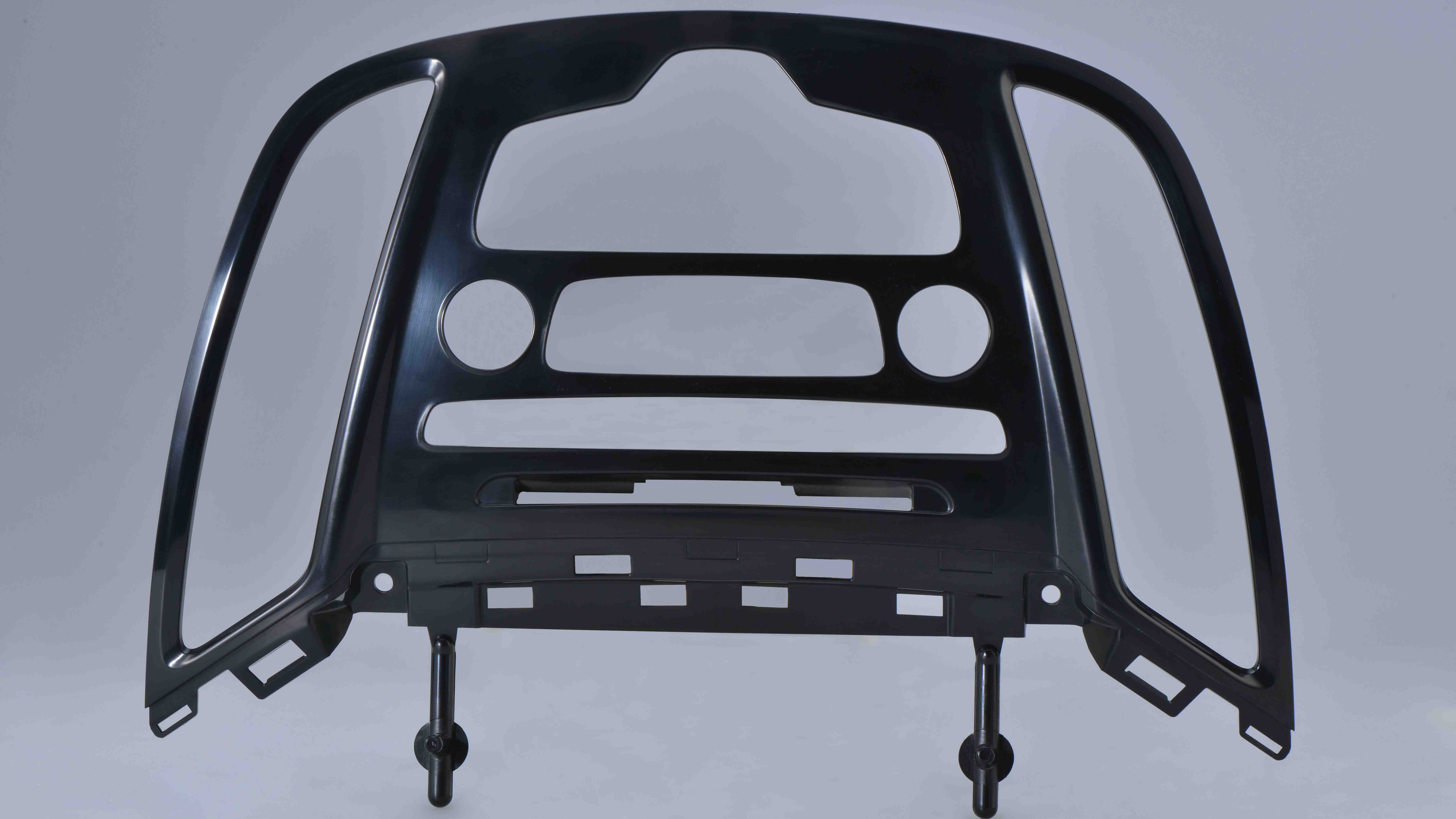
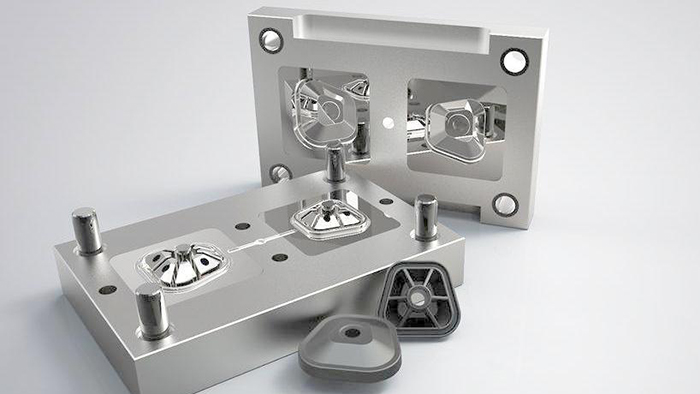
Injection molding, or injection molding for short, is a manufacturing method that creates parts by injecting material into a mold. It is a type of plastic processing technology.
In this process, plastic is placed into a hopper, which then heats and injects the plastic through a long chamber propelled by a reciprocating screw. It is then softened into a fluid state. A nozzle located at the end of the chamber forces the fluid plastic through the nozzle to cool it, closing the mold. As the plastic cools and solidifies, the semi-finished product exits the press.
This section introduces design guidelines to consider when designing injection molded parts. The image below is a simplified mind map created by the author. Save it as a different file to see a clearer view.
Understand the principles of injection molding and design parts that conform to the injection molding process.
After careful consideration, the author believes this is perhaps the first point that needs explaining, especially for beginners or those outside the industry. If you've only worked with metal processing, you'll need to specifically understand what injection molding is: as shown in the diagrams in the two subsections above. You can't use the same mindset as machining to make plastic parts, nor should you deliberately push the limits of injection molding to create parts that are inherently impossible to produce.
As shown in the image below:
Some might see this as innovation and force suppliers to manufacture it. But if you can afford the technology, others can too, and it will be copied by competitors in no time, making it a losing proposition.
From the author's perspective: designing injection molded parts is essentially designing a shell that can be demolded.
First, the parts must be able to be demolded, so they must conform to the demolding action and have a draft angle.
When plastic material changes from a molten state to a solid state, it will undergo a certain amount of dimensional shrinkage. As a result, the part shrinks and tightens around the punch and core. In order to facilitate the smooth demolding of the plastic part from the mold and prevent scratches on the surface of the part during demolding, the surface of the part parallel to the demolding direction should generally have a reasonable draft angle, as shown in Figure 3-27.
The factors that determine the draft angle are as follows:
1) Unless otherwise specified, the draft angle for parts is generally 1° to 2°;
//This is just the general direction; see the image below for details, and then look at the specific design.
2) For plastic parts with high shrinkage, a larger draft angle should be selected.
3) Smaller draft angles should be used for parts with high dimensional accuracy requirements.
4) The draft angle on the punch side is generally smaller than that on the die side to facilitate demolding of the part.
5) When the wall thickness of the plastic part is relatively thick, the molding shrinkage increases, so the draft angle should be larger.
6) The draft angle for textured and complex surfaces should be larger, and the size of the texture determines the size of the draft angle.
7) For glass fiber reinforced plastics, a larger draft angle is preferable.
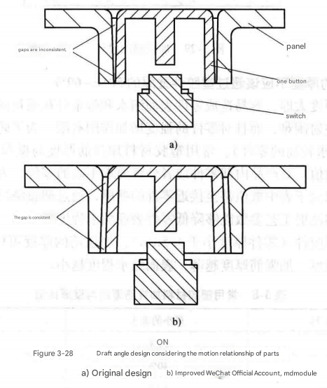
8) The size and direction of the draft angle should not affect the functionality of the product. For example, when two parts have a moving relationship, the size and direction of the draft angle at the mating point need to be considered; otherwise, it will affect the functionality of the product.
Example: Figure 3-28 shows a cross-sectional view of the button and panel on an electrical appliance. The button's function is to trigger the appliance's switch. The optimized design direction shown in the figure is: the draft angles of the panel and the button should be consistent.
9) Some planes of the part may not need to be set with draft angles due to functional requirements, but the mold needs to be designed with a side core-pulling structure, which makes the mold structure complex and costly.
10) Where the function and appearance of the part allow, the draft angle of the part should be as large as possible.
Smaller draft angles increase the likelihood of surface scratches and damage to parts during ejection; at the same time, smaller draft angles require mold surface polishing or complex mold ejection mechanisms, increasing mold costs.
//The draft angle for parts is generally 0.5° inward, 1° outward, and 3° for textured surfaces. This is not recommended but can be used as a reference.
Regarding draft angles, structural engineers should ideally be able to draw the draft angles for all part surfaces themselves. For uncertain surfaces, a draft angle of 0.5° should be used, and then negotiated with the mold manufacturer. As a second-best approach, the draft angles for textured surfaces and critical structures should be drawn by the engineer and then negotiated. Therefore, structural design often becomes a task that requires verbal negotiation.
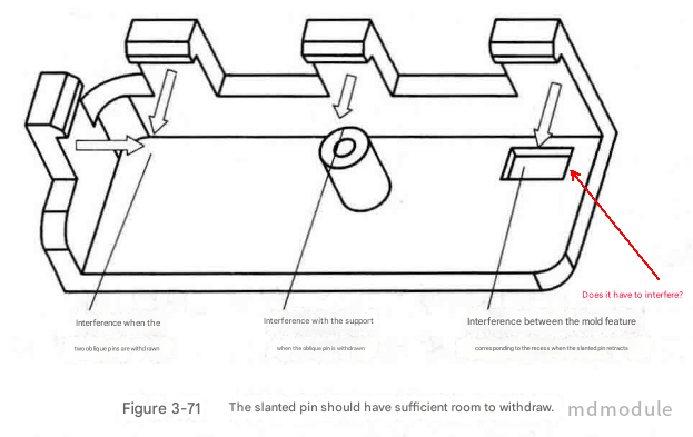
Clip-on structures are a common assembly method for plastic parts, formed by a lateral core-pulling structure using a slanted pin (or slider) in the mold. The slanted pin (or slider) has a travel distance from the clip during demolding. The part design needs to provide sufficient movement space for the slanted pin (or slider) to retract; otherwise, the slanted pin (or slider) may fail to retract or interfere with other features on the part (such as supports) during retraction, as shown in Figure 3-71.
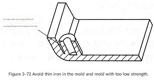
In plastic parts, if two features are very close together, the corresponding part on the mold will be a thin piece of iron, as shown in Figure 3-72. This can easily lead to low mold strength and short lifespan. Therefore, it is necessary to avoid thin iron and designs with too low strength on the mold.
In the design of plastic parts, the wall thickness is the primary parameter to consider. It determines the part's mechanical properties, appearance, injectability, and cost. In short, the selection and design of the part's wall thickness determines the success or failure of the design.
Due to the characteristics of plastic materials and the special nature of injection molding processes, the wall thickness of plastic parts must be within a suitable range; it cannot be too thin or too thick.
If the wall thickness is too thin, the flow resistance during injection is high, and it is difficult for the molten plastic to fill the entire cavity. Therefore, it is necessary to use higher-performance injection equipment to obtain higher filling speed and injection pressure.
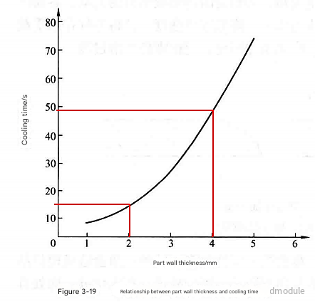
Excessive wall thickness increases the cooling time of parts (according to statistics, if the wall thickness of a part increases by 1 time, the cooling time increases by 4 times), increases the part forming cycle, and reduces the production efficiency of parts; at the same time, excessive wall thickness can easily cause quality problems such as shrinkage, porosity, and warping of parts.
Different plastic materials have different requirements for the appropriate wall thickness of plastic parts. Even the same plastic material produced by different manufacturers may have different appropriate wall thickness requirements. Table 3-7 shows the appropriate wall thickness ranges for commonly used plastic material parts. When the wall thickness of a plastic part approaches the upper or lower limit of the appropriate wall thickness values in the table, the product design engineer should consult with the plastic material manufacturer.

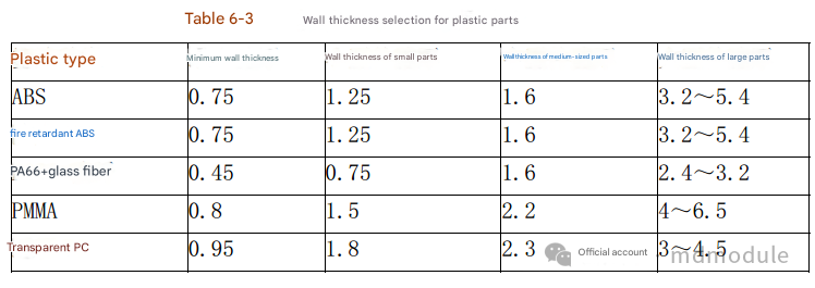
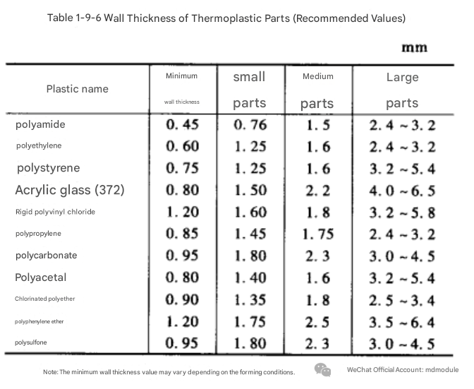
Since working in the furniture industry, this wall thickness data has truly become only a reference. Many chairs have plastic armrests (made of PP) with an average thickness of over 5mm. Therefore, wall thickness is an important know-how factor in injection molding, reflecting a company's overall manufacturing capabilities, including structure, materials, molds, and injection parameters. This requires regular observation, statistics, and data collection. Because a company's manufacturing level doesn't develop in leaps and bounds, wall thickness can only be used as a reference for parts with the same structure and material.
Key factors determining the wall thickness of plastic parts include:
1) Is the structural strength of the part sufficient? Generally speaking, the thicker the wall, the better the strength of the part. However, when the wall thickness exceeds a certain range, due to quality problems such as shrinkage and porosity, increasing the wall thickness will actually reduce the strength of the part.
2) Can the part resist demolding force during molding? If the part is too thin, it is easy to deform during ejection.
3) Whether it can withstand the tightening force during assembly.
4) When there are metal inserts, is the strength around the inserts sufficient? Generally, uneven shrinkage between metal inserts and the surrounding plastic material can easily lead to stress concentration and low strength.
5) Whether the impact force borne by the parts can be evenly distributed.
6) Is the strength of the hole sufficient? The strength of the hole can be reduced due to the influence of weld lines.
7) Under the premise of meeting the above requirements and ensuring that injection molding does not cause quality problems, the wall thickness of plastic parts should be minimized as much as possible. This is because thicker wall thickness will not only increase material costs and part weight, but also prolong the part molding cycle, thereby increasing production costs.
Figure 3-19 shows the relationship between the wall thickness and cooling time of a certain ABS plastic part.
To ensure and improve the strength of parts, product design engineers often prefer to choose thicker part walls.
In fact, choosing a thicker wall thickness to ensure and improve part strength is not the best approach. Part strength can be increased by adding reinforcing ribs, designing curves or wavy cross-sections, which not only reduces material waste but also shortens the injection molding cycle.
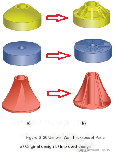
Ideally, the wall thickness distribution of a part should be uniform across any cross-section. Uneven wall thickness will cause uneven cooling and shrinkage, resulting in defects such as surface shrinkage, internal porosity, warping, and difficulty in ensuring dimensional accuracy.
Examples of common uniform wall thickness designs for plastic parts are shown in Figure 3-20.
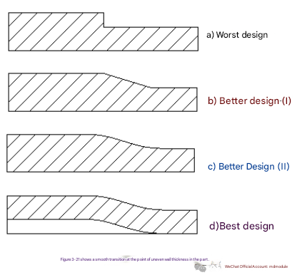
If a uniform wall thickness is impossible to achieve, then at least a smooth transition between thick and thin sections must be ensured to avoid abrupt changes in wall thickness. Dramatic changes in wall thickness affect the flow of molten plastic, easily creating stress marks on the back of the plastic, impacting the product's appearance; they also tend to cause stress concentration, reducing the strength of the plastic part and making it difficult to withstand loads or external impacts.
Figure 3-21 shows the wall thickness design at the uneven wall thickness of the four types of parts.
The worst wall thickness design is shown in Figure 3-21a, where the wall thickness of the part changes drastically;
A better wall thickness design is shown in Figures 3-21b and 3-21c, with a uniform transition between thick and thin sections. Generally, the length of the transition area is three times the thickness.
The best wall thickness design is shown in Figure 3-21d. Not only does the wall thickness transition smoothly, but a hollow design is also used at the wall thickness point. This ensures that the part does not shrink and also guarantees the strength of the part.
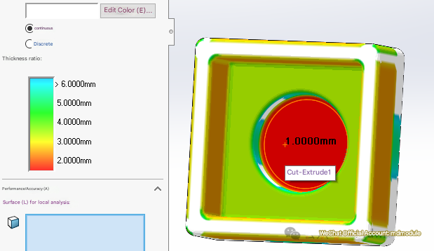
The wall thickness of plastic parts can be viewed using the wall thickness analysis function in the software, which provides a more intuitive and clear view.

Sharp corners should be avoided on both the inside and outside of plastic parts. Sharp corners can hinder the flow of molten plastic, easily causing appearance defects. Furthermore, sharp corners can cause stress concentration, reducing the strength of the part and leading to failure under load. Therefore, rounded corners should be added to the sharp corners of plastic parts to ensure a smooth transition.
Therefore, structural engineers should add rounded corners to 3D models whenever possible. 3D models are used when creating molds for plastic parts.
The design of the external rounded corners of the plastic part is shown in Figure 3-22.

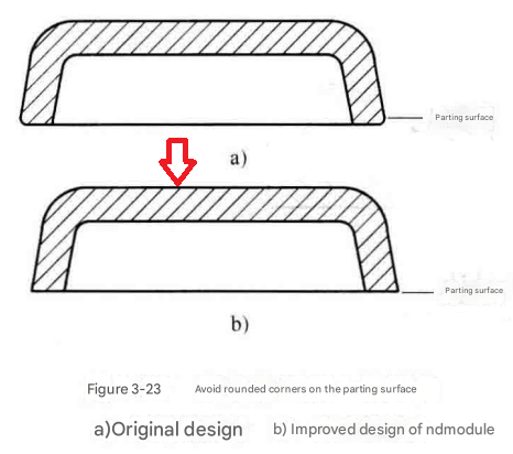
Of course, avoiding sharp corners on the outside of parts cannot be generalized. Rounded corners at the parting surface can complicate the mold structure, increase mold costs, and make the part prone to breakage, affecting its appearance. A right angle design at the parting surface is better, as shown in Figure 3-23.
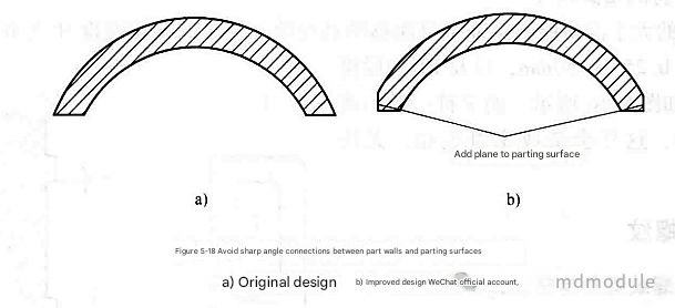
If a flat surface of approximately 1.5m is added at the joint, the flash and gate can be easily removed during the removal process, as shown in Figure 5-18. (This is generally not necessary for injection molded parts.)
To avoid creating sharp corners in the flow direction of molten plastic in plastic parts, as shown in Figure 3-24, where the arrows indicate the flow direction of the molten plastic. In the original design, sharp corners easily lead to trapped air during injection , causing localized high temperatures that decompose the plastic and create surface defects . Sharp corners also tend to generate internal stress . In the improved design, sharp corners are avoided through optimization, ensuring smooth flow of the molten plastic.

Stress concentration is one of the main causes of failure in plastic parts. It reduces the strength of the parts, making them more susceptible to failure under impact and fatigue loads. Stress concentration often occurs at sharp corners. Plastic parts should avoid sharp corner designs and incorporate fillets to reduce and prevent stress concentration. Sharp corners are prone to appear at the junctions of the main wall and side walls, the wall and reinforcing ribs, and the wall and support columns. The relationship between the internal fillet radius and the stress concentration factor is shown in Figure 3-25, where T is the wall thickness, R is the internal fillet radius, and p is the load on the part.
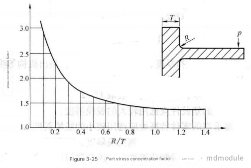
As can be seen from Figure 3-25, when R < 0.3T, the stress increases sharply; when R > 0.8T, there is basically no stress concentration phenomenon.
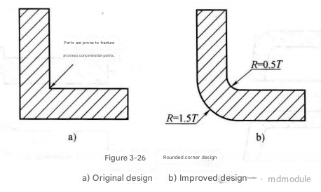
Generally, the inner fillet radius (R) at the joint of a part's cross-section is 0.5T, and the outer fillet radius is 1.5T. This ensures uniform wall thickness and reduces stress concentration at the joint, as shown in Figure 3-26. However, the fillet radius should not be too large, otherwise it may cause excessive local wall thickness, resulting in shrinkage.
Electrical discharge machining (EDM) is a commonly used machining method in mold making, especially for complex curved surfaces. This machining method requires the use of electrodes.
The sharp corners, edges, and other protruding parts of the electrode wear out faster during electrical discharge machining than the flat parts.
Therefore, some responsible mold engineers will actually require parts to have rounded corners, or they will add a minimum 0.2 rounded corner to the plastic mold themselves.
The following is a conversation between the author and a mold engineer about rounded corners (the purpose was to confirm whether all edges of the model should be rounded).

This is merely the author's summary and suggestions.
Modeling rounded corners on plastic parts is not something that can be done successfully in one go. It is recommended to follow these requirements.
As shown in the national standard GB26099, the model for rounded corners is as follows:

As mentioned above regarding the requirement to avoid sharp corners, since external sharp corners, flow directions, and connections all require rounded corners, this means the entire plastic model needs rounded corners. Therefore, the author suggests that all edges of the plastic model should be rounded. Rounded corners on parting lines can be removed later by the mold engineer.
Steps for adding rounded corners: Generally, first use edge rounded corners on the important edges, then on the less important edges, and finally use face rounded corners on the remaining edges. Face rounded corners are used less often because they are difficult to control and modify.
You can apply rounded corners by category, applying them multiple times, rather than applying all the rounded corners at once, as this makes them harder to control and modify.
Of course, some special, obviously rounded corners can be directly marked with an R1 value.
The strength of plastic parts is always a key concern for product design engineers. Compared to metal parts, plastic parts generally have lower strength, but through proper part design, their strength can be significantly improved, thereby expanding their application range.
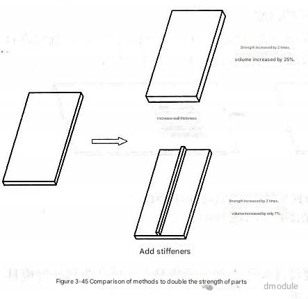
While increasing wall thickness can improve part strength during design, this is often an inefficient approach. Increasing wall thickness not only increases the weight of the plastic part but also increases the risk of shrinkage, bubbles, and other defects, while simultaneously increasing injection molding time and reducing production efficiency. The correct method to improve part strength is to add reinforcing ribs, not wall thickness. Adding reinforcing ribs increases strength while preventing shrinkage, bubbles, and reduced production efficiency. However, the dimensions of the reinforcing ribs must adhere to design principles; excessively thick ribs can also cause shrinkage and bubbles. Figure 3-45 illustrates two methods to double part strength: increasing wall thickness and maintaining the same wall thickness while adding reinforcing ribs. To double the strength, increasing wall thickness requires a 25% increase in part volume, while adding reinforcing ribs only requires a 7% increase. Therefore, adding reinforcing ribs is the best method to improve part strength.

//Note: Reinforcing ribs can reduce overall deformation of parts, but adding them will cause surface shrinkage, affecting the appearance. Therefore, when the appearance of a part is truly important, consider thickening the part rather than adding reinforcing ribs.
It is important to note that reinforcing ribs can only strengthen the plastic part in one direction. The direction of the reinforcing ribs must take into account the load direction; otherwise, the reinforcing ribs will not increase the part's ability to resist loads, as shown in Figure 3-47.

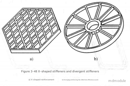
If a part is subjected to loads in multiple directions or torsional loads, adding X-shaped or divergent reinforcing ribs can improve its strength, as shown in Figure 3-48. In everyday life, the back of plastic stools often uses X-shaped or divergent reinforcing ribs to enhance the strength of the parts.
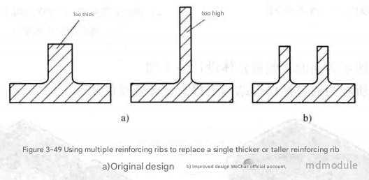
Multiple reinforcing ribs are more effective at increasing the strength of parts than a single, thicker or taller reinforcing rib, while also avoiding quality problems such as surface shrinkage or incomplete injection at the top of the reinforcing rib. Therefore, when a single reinforcing rib is too tall or too thick, it can be replaced by two smaller, moderately thick reinforcing ribs, as shown in Figure 3-49.
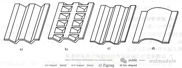
The strength of plastic parts can be improved by designing reinforcing profiles. Common reinforcing profiles include serrated, sawtooth, and arc shapes, as shown in Figure 3-50. A disadvantage of this method is that the part cannot provide a flat surface, making it unsuitable in certain situations.
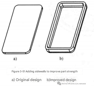
Avoid flat plastic part designs, as flat plastic parts have very low strength. The strength of the parts can be increased by adding side walls around them, as shown in Figure 3-51.
The sidewall can be a simple straight wall. When conditions permit, curved sidewalls or sidewalls with reinforced cross-sections can improve the strength of the part, as shown in Figure 3-52.
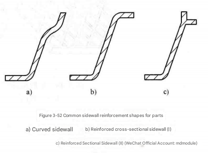
Figure 3-53 shows an example of a curved sidewall box design.
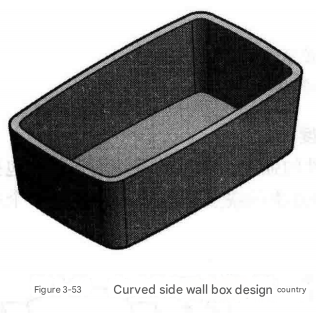
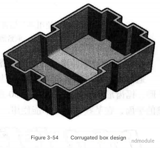
Figure 3-54 shows an example of improving the strength of a box through a corrugated structure.
Stress concentration commonly occurs at sharp corners , areas of dramatic wall thickness changes , and in holes, slots, and metal inserts . Stress concentration significantly reduces the strength of a component , leading to failure under impact loads. Component design should avoid stress concentration. To prevent stress concentration, component design should strictly adhere to the design guidelines outlined in the preceding sections.
During part injection molding, when molten plastic passes through holes, channels, supports, or areas with large parts, or when multiple gates are used, the molten plastic will flow in two or more directions. When molten plastic from two directions meets, a weld line will be generated in this area . The weld line area is one of the areas with the lowest strength in the part and one of the areas most prone to failure. Therefore, the location and number of gates must be reasonably set to avoid the part bearing loads in the weld line area. As shown in Figure 3-55, in the original design, the gate position caused the weld line to be located exactly at the load-bearing point of the part, making the part prone to failure under load. In the improved design, the gate position was adjusted so that the weld line was located away from the load-bearing point of the part, greatly improving the reliability of the part.
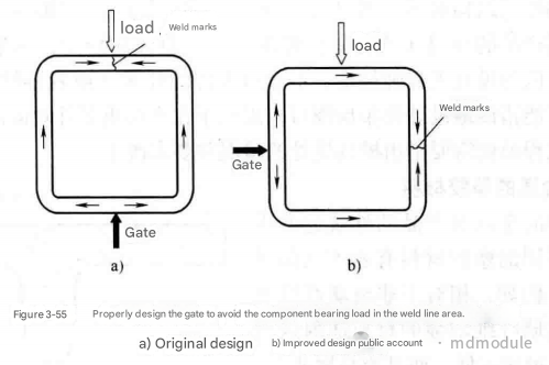
The presence of weld lines can easily cause products to fail strength tests. In actual injection molding, the injection molding technician can be instructed not to fill the mold completely, thus observing the location of the weld lines in actual production and determining whether structural modifications are necessary.
1) Glass fiber reinforced plastics are often used to replace ordinary plastic materials to increase the strength of plastic parts. It should be noted that glass fiber reinforced plastics only increase the strength of the part in the direction of the glass fibers.
//This is hard to say. Taking PP material as an example, a high GF content increases the material strength, but it is also more prone to brittleness and breakage. High strength materials are easily deformed but not easily broken. And just because it deforms often means it has passed testing. 2) Plastic parts are more capable of withstanding compressive loads than tensile loads.
//Please refer to the material property testing and property table. 3) When subjected to tensile loads, design consistent part profiles to evenly distribute the load. 4) Avoid subjecting parts to circumferential loads. Parts (such as metal inserts) are prone to cracking and failure when subjected to circumferential loads. 5) When subjected to impact loads, maintain the integrity of the part profile and avoid gaps and stress concentrations in the part profile in the direction of the impact load.
In today's increasingly competitive market, product appearance has become a crucial factor in attracting consumers. Due to the inherent characteristics of plastic materials and the injection molding process, plastic parts are prone to appearance defects such as shrinkage, bubbles, weld lines, trapped air, and jetting, severely impacting their overall quality. These appearance quality issues primarily stem from problems in part design, mold design, and incorrect injection molding parameters. For product design engineers, addressing appearance quality issues should begin with part design, especially for exterior components; appearance requirements for internal parts can be more relaxed. From a part design perspective, besides adhering to the design guidelines outlined above, the following aspects can help improve the appearance quality of plastic parts.
The selection of plastic materials plays a crucial role in the appearance of a product, with different materials exhibiting varying degrees of aesthetic quality. For instance, compared to non-glass fiber reinforced materials, glass fiber reinforced materials generally have lower aesthetic quality after injection molding and are more prone to warping.
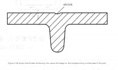
Surface shrinkage is one of the most common appearance defects in plastic parts. Shrinkage generally occurs on the outer surface of parts with thicker walls, such as the outer surface of parts where reinforcing ribs or pillars connect to the wall, as shown in Figure 3-56.
Where permissible, surface shrinkage of plastic parts can be concealed by using U-shaped grooves, surface discontinuity design, and surface texturing, as shown in Figure 3-57.
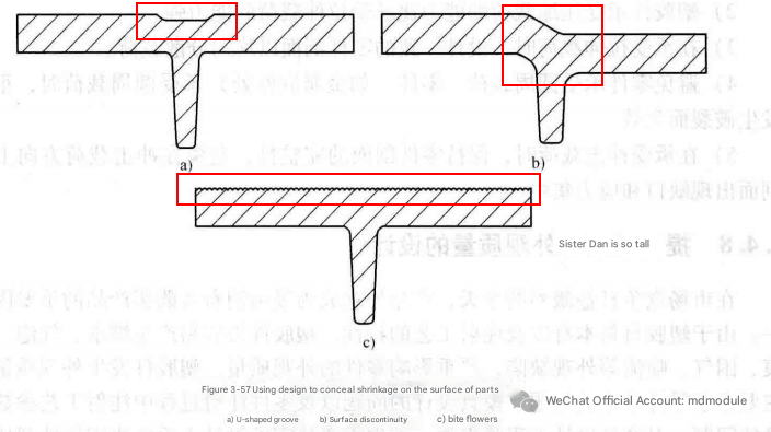
//Usually, reducing the thickness of the reinforcing ribs or increasing the wall thickness is used to improve surface shrinkage.
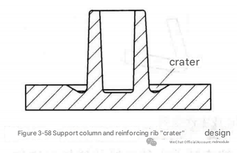
Removing material from thick sections of the support or reinforcing ribs (referred to as "cratering" in Taiwan) can significantly reduce the likelihood of reduced appearance in parts, as shown in Figure 3-58. However, this "cratering" design will, to some extent, reduce the strength of the support or reinforcing ribs.
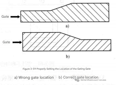
The farther a part is from the gate, the more prone it is to surface shrinkage. For critical surfaces of a part where surface shrinkage is critical, the gate's location can be strategically designed to be close to these areas, reducing the likelihood of surface shrinkage. Simultaneously, the gate's position should ensure that the molten plastic flows from the thickest part to the thinnest part, as shown in Figure 3-59. If the molten plastic flows from the thinnest to the thickest part, the thinnest part cools and solidifies first, making the surface of the thickest part prone to shrinkage, while internal air bubbles are more likely to form.
Part deformation not only causes poor dimensional accuracy, leading to assembly problems and affecting the functionality of the part, but also affects its appearance. There are many reasons for part deformation, mainly including four aspects: different shrinkage ratios in the direction of plastic melt flow and in the cross-sectional direction, uneven cooling, uneven wall thickness, and asymmetrical geometry.
1) The different shrinkage ratios of the parts in the direction of plastic melt flow and in the cross-sectional direction.
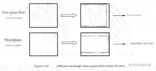
The different shrinkage ratios of the part in the direction of plastic melt flow and in the cross-sectional direction cause the part to deform, as shown in Figure 3-60.
Non-glass fiber reinforced materials have a larger shrinkage rate in the direction of plastic melt flow than in the cross-sectional direction, resulting in greater shrinkage of the plastic in the direction of plastic melt flow and less shrinkage in the cross-section, causing deformation of the parts;
Conversely, glass fiber reinforced materials exhibit a smaller shrinkage rate in the direction of plastic melt flow compared to the cross-sectional direction. This results in less shrinkage in the direction of plastic melt flow and greater shrinkage in the cross-section, leading to deformation of the parts.
2) Uneven cooling of parts
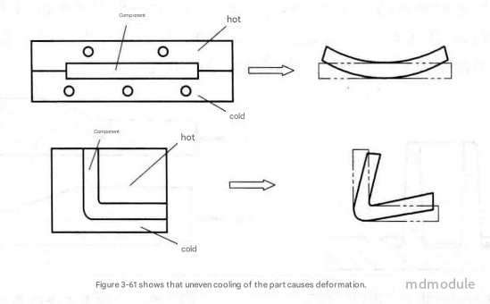
Uneven cooling along the wall thickness of a part can cause it to deform. Uneven cooling may be caused by an unbalanced water channel design in the injection mold, or by the fact that the heat dissipation area on the outer side of the part is larger than that on the inner side, resulting in slower heat dissipation and cooling on the outer side and faster heat dissipation and cooling on the inner side (see Figure 3-61). The direction of part deformation is always towards the hotter side of the part.
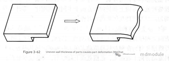
3) Uneven wall thickness causes deformation. The shrinkage rate of plastic parts increases with the increase of wall thickness. The shrinkage difference caused by uneven wall thickness is one of the main reasons for the deformation of thermoplastic parts. Specifically, the change in the wall thickness of the plastic part cross section usually causes differences in cooling rate and crystallinity, resulting in differences in part shrinkage and part deformation, as shown in Figure 3-62.
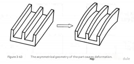
4) Asymmetrical geometry of parts causes deformation. Asymmetrical geometry of parts can lead to uneven cooling and differential shrinkage, causing deformation, as shown in Figure 3-63.
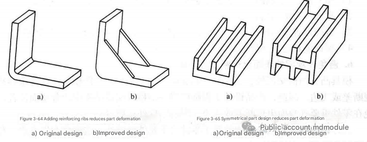
5) Predict the deformation trend of parts and reduce the deformation through design. The causes and methods of part deformation have been discussed above, but this is not the focus. The focus of product design is to predict the deformation trend of parts and reduce or even avoid the occurrence of part deformation through part design optimization, as shown in Figures 3-64 and 3-65.
When two plastic parts are fitted together, gaps and discontinuities (where the surface of one part is higher than the surface of the other part) will always exist due to manufacturing and assembly errors. This will affect the appearance of the product, as shown in Figure 3-66a.
Artificial grooves can be designed to conceal gaps between two plastic exterior parts, thereby improving the product's appearance. Two common artificial groove designs are shown in Figures 3-66b and 3-66c.
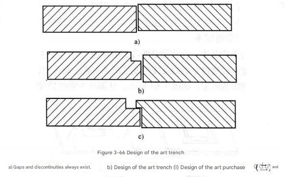
The size of the decorative groove depends on the product dimensions; for example, the decorative groove for a computer case panel is 0.5mm x 0.5mm . Of the two decorative groove designs, the second method is superior to the first. The first design, due to the gap, allows consumers to see the internal parts of the product and offers no dust protection. When the relationship between two exterior plastic parts is front-to-back or top-to-bottom, such as the top and bottom covers of a mobile phone, the difference in height becomes a factor affecting the appearance of the parts. If the rear/bottom part is higher than the front/top part, the product becomes very unsightly. Therefore, in this case, the decorative groove design should be such that the rear/bottom part is lower than the front/top part .
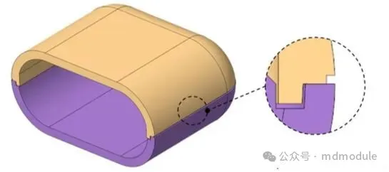
Weld lines are also a common surface defect in plastic parts and need to be avoided. Specific methods are as follows: 1) Surface texturing of plastic parts can partially cover weld lines, but cannot completely conceal them. 2) Painting can cover weld lines. 3) Properly design the location and number of gates to avoid weld lines on important surface areas of the parts. 4) Ensure proper ventilation in the mold.
Discontinuities or flash can easily occur at the junctions of the punch and die, between cores, and between the core and the punch/die. Therefore, product design engineers should carefully inspect the parting surface location in the mold structure to avoid discontinuities or flash on important appearance surfaces of parts, which could affect the appearance quality of the parts.
Additionally, avoid placing ejector structures on critical surface areas of parts, as this can create flash. This is especially important for transparent plastic parts.
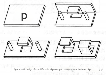
Injection molds are typically expensive. Designing multifunctional plastic parts can offset mold costs, thereby reducing part development costs. Furthermore, because plastic parts can have complex shapes and internal structures, one plastic part can often replace two or more parts manufactured using traditional methods. Multiple plastic parts can sometimes be combined into a single part to save costs. For example, in electronic and electrical products, proper cable routing and securing are crucial for heat dissipation and electromagnetic interference control. Cable securing is usually achieved using dedicated cable ties or clips. However, adding simple features to the plastic part can achieve cable securing, as shown in Figure 3-67, thus reducing the need for cable ties or clips.
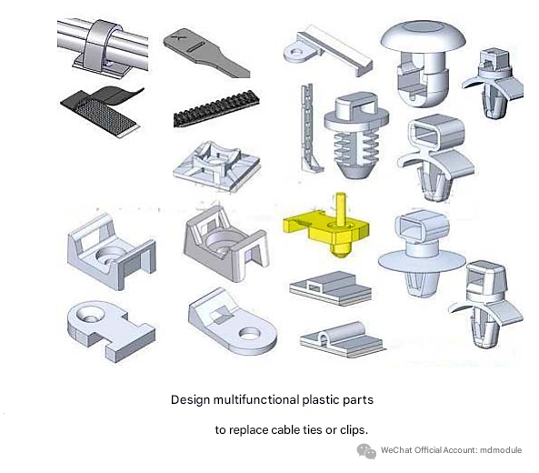
Plastic materials are a product of the petroleum industry. With dwindling oil reserves, the price of plastic materials is constantly rising. In recent years, when oil prices soared, the surge in plastic material prices even forced Chinese home appliance manufacturers to raise prices. Therefore, while ensuring product functionality, component design should use as little material as possible. Less material reduces component costs and avoids increasing injection molding time and costs. When reducing material usage, the following should be noted: 1) Improve component strength by adding reinforcing ribs rather than increasing wall thickness. 2) Remove material from thicker sections of the component.
The KISS principle, discussed in the Design for Assembly (DFA) chapter, also applies to the design of individual parts; for plastic parts, simplicity is key. Complex shapes and structures not only increase mold complexity and cost but also negatively impact part quality and performance. Plastic parts should be designed as multifunctional as possible, but multifunctionality does not equate to complexity. If a multifunctional design increases overall product cost, it defeats the purpose of multifunctionality, one of which is to reduce product cost.

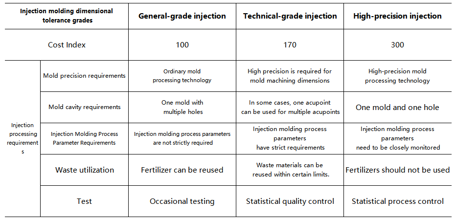
① In applications requiring high dimensional accuracy, choose plastics with low shrinkage.
② There are additional alignment errors at the mating points of the mold cavity and inserts, inclined pins and sliders, so avoid imposing strict tolerance requirements in this area.
③ Predict the warpage area of the plastic part and avoid imposing strict tolerance requirements in that area; warpage can usually be reduced by adding reinforcing ribs.
Undercuts refer to the characteristics of parts that prevent normal demolding, such as openings on the upper side and bosses on the side of the mold opening direction. In molds, undercuts are achieved through side parting and core-pulling mechanisms , which are among the more complex structures in molds and also a significant factor in increasing mold costs. Commonly used side parting and core-pulling mechanisms include inclined pins and sliders. To reduce mold costs, avoiding undercuts in part design is an important approach. (1) Some external undercuts can be avoided by redesigning the parting surface, as shown in Figure 3-68. Redesigning the parting surface can prevent external undercuts from preventing smooth demolding of parts.

(2) Redesign part features to avoid part undercuts
Many undercut features on parts can be eliminated through feature optimization design, thereby avoiding the use of side core-pulling mechanisms and reducing part mold costs, as shown in Figure 3-69.

As shown in Figure 3-70, in the original design, the part has an undercut, which requires a side core-pulling structure such as a slanted pin or a slider for demolding. By redesigning the part features, the use of a side core-pulling mechanism can be avoided. The improved design provides four methods, as shown in Figures 3-70b, c, d and e.

Once a plastic injection mold is manufactured, modifying the mold is extremely costly. Incorrect plastic part designs often increase the number of mold modifications, raising mold costs and consequently increasing the cost of the parts and the final product. Therefore, the design of plastic parts should aim to minimize or even avoid mold modifications.
When designing plastic parts, injectability should be fully considered. Good injectability results in high-quality injection molded parts, fewer mold modifications, and lower mold modification costs. Conversely, if injectability is not considered in the design, poor injectability leads to low-quality injection molded parts, more frequent mold modifications, and higher mold modification costs. Therefore, plastic part design must adhere to the plastic part design guidelines outlined in this chapter.
Of course, mold modifications may also be necessary because the plastic part cannot fulfill its intended function in the entire product. Therefore, before mold development, product design engineers need to improve and optimize the part design through CAE analysis, motion simulation, sample making, and other means to ensure that the part design is flawless before proceeding with mold design and development, thereby reducing product design modifications after mold manufacturing is completed.
Removing material from a mold is relatively easy and inexpensive to modify; adding material to a mold is more complex and expensive to modify. Therefore, design modifications for plastic parts should ideally involve removing material from the mold rather than adding material, and vice versa. When designing a part, if you are unsure about its dimensions, you can leave a certain margin and then verify the design by removing material.
Methods for fixing plastic parts include clips, screws, hot melt welding, and ultrasonic welding. Clips allow for quick assembly and disassembly, and they are also the cheapest option. Using clips can reduce the cost of parts while meeting product assembly and functional requirements.
The number of cavities in a mold affects the processing efficiency of plastic parts. More cavities mean a more complex mold, but also higher processing efficiency, lower processing costs, and less runner material per part. Given the expected production capacity requirements, the number of cavities can be rationally selected by calculating the cost of the plastic part (material cost, mold cost allocation, and processing cost). Furthermore, choosing a suitable runner system also helps reduce the cost of plastic parts. Traditional cold runner systems suffer from material loss, especially for expensive plastic materials. Hot runner systems, on the other hand, have virtually no material loss. Moreover, the absence of a runner system shortens the cooling time of the plastic part and the mold opening stroke, thus reducing the molding cycle. Additionally, there is no need for gate trimming or runner recycling, which facilitates production automation. However, its disadvantage is that it is more expensive than traditional cold runner molds.
1) Design parts and molds so that the gate can be automatically removed or hidden inside the product to avoid secondary processing of the gate.
2) Hide the parting surface inside the product to avoid secondary cutting and processing of the parting surface.
Some features are unique to injection molded parts. For example, reinforcing ribs, supports, and injection holes.
These typical design features are very suitable for designers to accumulate, and there are many design guidelines available. The author also intends to describe them in chapters.
There are many ways to assemble injection molded parts. Common assembly methods can be roughly divided into four categories: snap-fit, mechanical fastening, hot melt, and welding. Each type of assembly method has its own advantages and disadvantages, as shown in Table 3-11.
Product design engineers should select appropriate assembly methods based on the product's assembly requirements and the factory's existing assembly equipment and technology in the initial stage of product design.
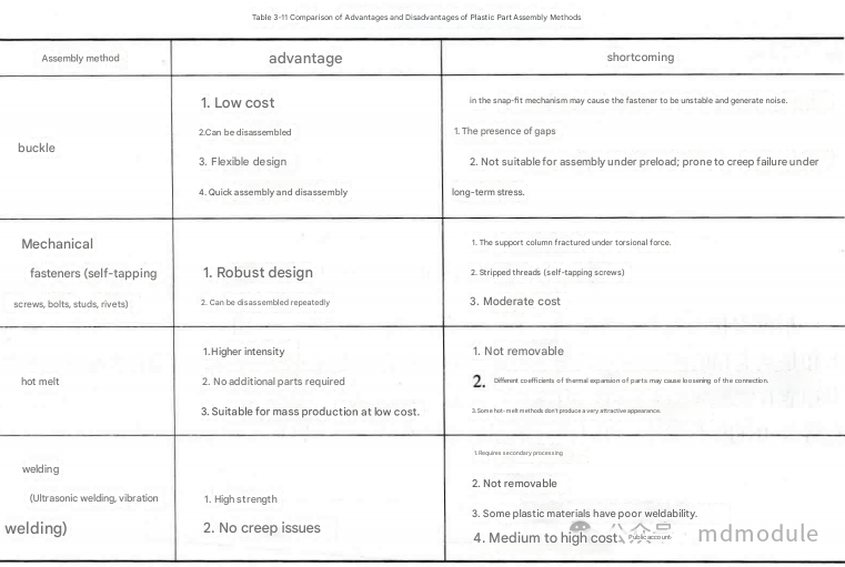
Of course, plastic parts can be assembled using a combination of the methods mentioned above. By combining the strengths of different methods, unexpected results can be achieved. For example, the combination of clips and screws not only ensures a stable fixing effect but also makes assembly simple and quick.
From an assembly perspective, welding, snap-fitting, and hot-melt assembly takes significantly less time than mechanical fastening, so the overall cost is often lower than that of mechanical fastening, which is also one of the current design trends.
However, given the company's current processing capabilities and reliability requirements, a more comprehensive consideration is needed.
The assembly structure of plastic parts is also a major challenge and a place where errors are prone to occur later. This will be described in separate chapters.
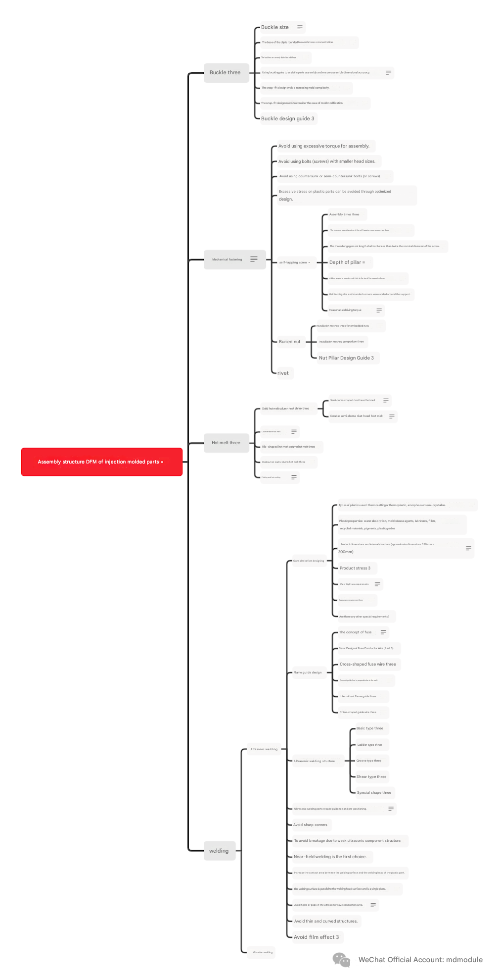
DFMA (Dual Principles of Management and Analysis) should be applied practically, followed beforehand, and supplemented afterward. An example table is shown below:

Reposted from:https://mp.weixin.qq.com/s/GQSqO0wBuSrBsYDQoo45xw