-
Engineering design team
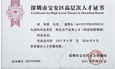
The engineering design team of the company is more than 35 people, including veteran designers with more than 10 years of experience, as well as high-level talents from Baoan District of Shenzhen. The company has obtained more than 20 national patents. After 14 years of precipitation, the company has obvious technical advantages in the industry in the following aspects.
-
-

-
Complex mold structure
-
-
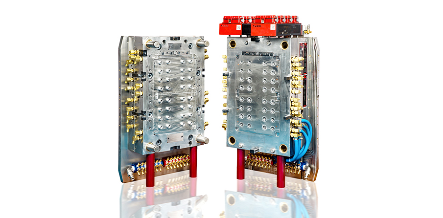
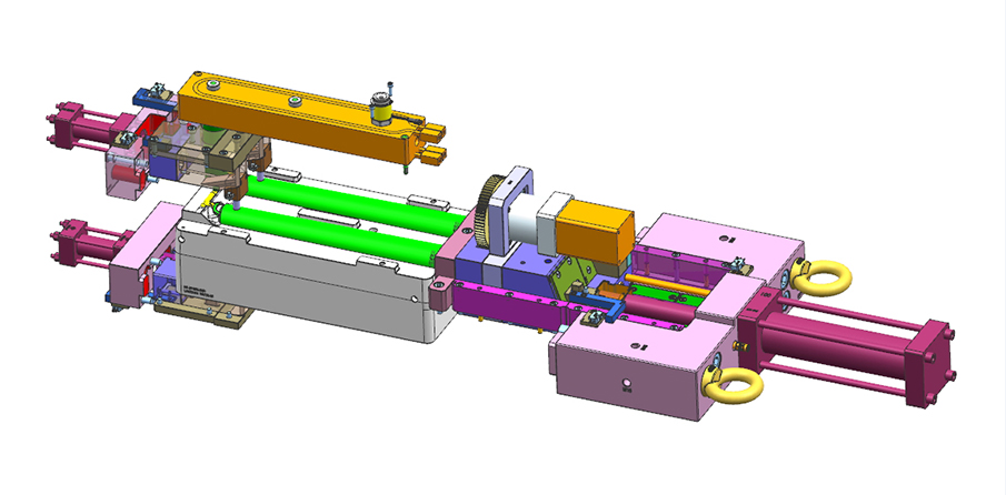
We can process all kinds of mold with complex structure to meet the production needs of different customers.
In this example, the length of the product is 600mm, and the middle core is sealed. The difficulty lies in the need to ensure that the product core cannot be eccentric and the end of the core needs to be extracted. In terms of the mold structure, the front-end oil cylinder is used in manufacturing to support the core.
contact us>High precision mold design and processing In this case, the 10ml virus collection tube high precision injection mold designed and manufactured by us for Daankiin is used for nucleic acid detection of the novel coronavirus. Five sets have been delivered. A 30ml virus collecting tube with high precision injection moulds has also been launched, with six sets delivered so far.
The dimensional accuracy of high precision mold reaches 0.002mm
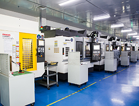
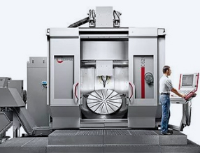
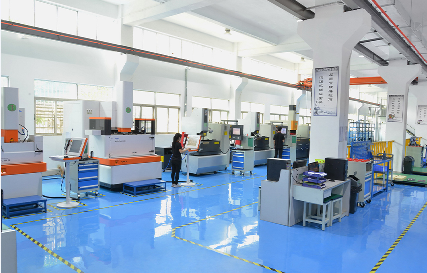
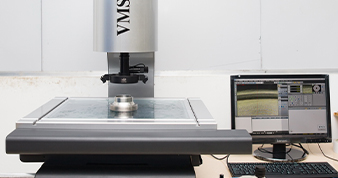
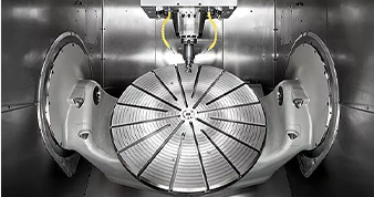
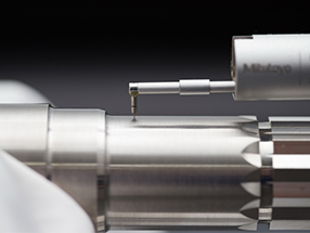
In terms of equipment, we have HERMLE 5-axis CNC machining center, AGIE spark machine, Sodick spark machine, Okuma, FANUC and other precision mold processing equipment to ensure the machining accuracy of the mold.
contact us>-
-
Mode flow analysis
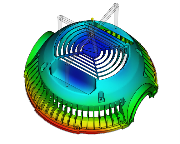
Pressure result at speed/pressure switch
The pressure results for the speed/pressure switch are generated by filling analysis and show the distribution of pressure along the flow path in the die when switching from speed control to pressure control.
01
-
-
Mode flow analysis
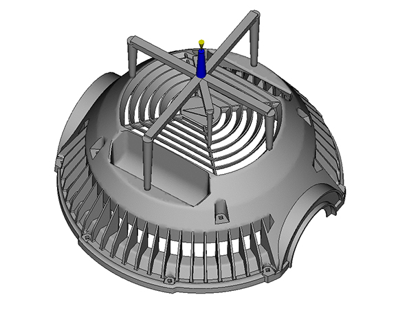
Filling time result
The filling time results show the position of the flow front at regular intervals when the cavity is filled.
02
-
-
Mode flow analysis
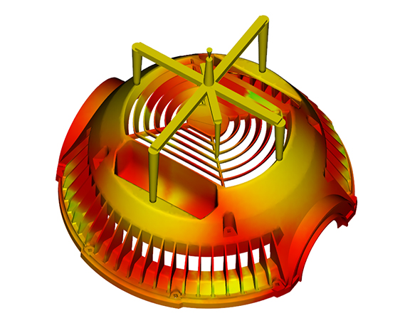
Flow front temperature results
The flow front temperature result is generated from the fill analysis and shows the polymer temperature when the flow front reaches a specified point located in the center of the plastic cross section.
03
-
-
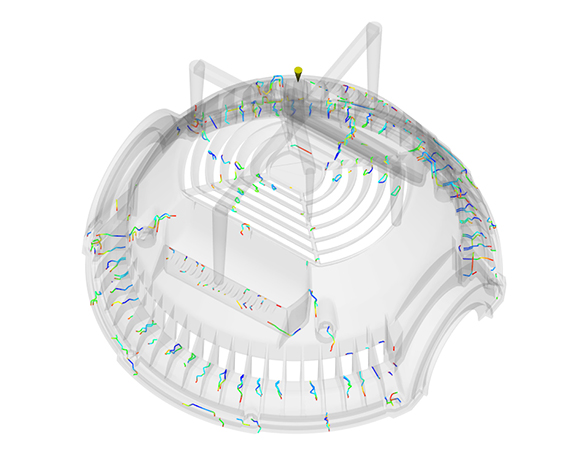
Mode flow analysis
Weld result
The fused wire results show the confluence Angle when two flow fronts meet. The display position of the fuse line can identify structural weaknesses and/or surface defects.
04
-
-
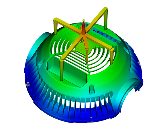
Mode flow analysis
Deformation result
The deformation results show the deformation at each node of the part (warp or stress analysis) or at each node of the gold wire or wafer (microchip package analysis).
05
- 1 Next item: Filling time result
- 2Next item: Flow front temperature results
- 3Next item: Weld result
- 4Next item: Deformation result
- 5Next item: Pressure result at speed/pressure switch
Form-following cooling technique
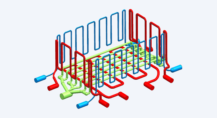
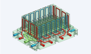
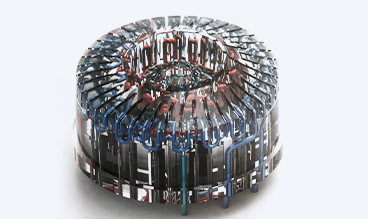
The traditional cooling method in mold manufacturing can only add a straight line of water in the thick area at the bottom of the mold, and the thin wall position can not achieve cooling, resulting in local shrinkage marks and a long cooling time. The mold pouring surface is a thin-wall structure, and the traditional cooling water processing method cannot realize adding water inside the thin-wall structure, so it is necessary to use metal 3D printing method to meet the full cooling of each part. The 3D printing of metal was used to realize the processing of the cooling flow path in the thin wall position of the die inserts. In this way, the special channels inside various cores and inserts are produced with the help of 3D printing technology, whose structure and form perfectly adapt to the geometry of special inserts and their functions in the mold. In order to achieve higher regulation efficiency, the runner must be close to the outer surface of the component. After preliminary analysis and optimization design, the water inside the mold has a good cooling effect.
Processing thermal deformation management
-

-
The whole processing workshop is constant temperature and humidity, and the constant temperature and humidity are kept in the process of processing, testing and assembly, so as to maximize the control of the deformation of parts caused by the change of ambient temperature and humidity.
01
-

-
High precision CNC machining center, through the original environmental thermal displacement control and spindle thermal displacement control, when the environmental temperature changes, automatically make the machine to maintain the best stable state, can achieve the most ideal machining accuracy.
02
-

-
For ultra-precision assembly parts, the shaft is inserted into the hole at a low temperature so that it can maintain stable operation at operating temperature.
03

