




Q1: What is injection speed?
Injection speed refers to the speed at which the screw moves forward during the injection phase, injecting molten plastic into the mold cavity. It is generally expressed in two ways:
Screw travel speed: This refers to the distance the screw travels per second. This is a value that can be visually represented on the injection molding machine, measured in mm/s or in/s.
Mel flow rate: This refers to the flow rate of the melt as it passes through the gate. This is the actual flow state of the melt within the mold cavity, but it cannot be directly measured.
Q2: What are the effects of injection speed?
1: Impact on product appearance.
l High-speed injection: The melt flows at high speed across the mold cavity surface, better replicating the gloss of the mold surface, resulting in a bright and smooth product surface. This is crucial for high-gloss surfaces (such as LCD TV casings and car grilles).
l Low-speed injection: The melt front advances slowly, and after contacting the cold mold wall, it cools and solidifies rapidly. Surface replication is poor, easily leading to a hazy or matte product surface.
l Flow marks and weld lines:
u Flow marks: Usually caused by slow injection speed through the gate, resulting in cooling of the melt front. Increasing the injection speed keeps the melt front at a high temperature, eliminating or reducing flow marks.
u Weld lines: Formed when two melt streams merge. High-speed injection increases the melt temperature at the merging point, allowing molecular chains to fuse and intertwine better, significantly reducing the strength and visibility of weld lines.
l Gas streaks and scorching:
u Gas streaks: If the speed is too high, the melt may "jet" (serpentine) out of the gate instead of spreading smoothly, causing gas to be trapped inside, forming serpentine or gas streaks. In this case, the injection speed needs to be reduced or the gate design changed.
u Scorching: Excessive speed rapidly compresses air within the cavity, generating instantaneous high temperatures that cause the plastic to decompose and carbonize, leaving scorch marks on the product (usually located in areas with poor venting).
2. Impact on the internal quality of the product.
l Molecular orientation and internal stress:
u Plastic molecules have a long-chain structure. During high-speed injection, the melt is subjected to intense shearing, stretching the molecular chains and aligning them along the flow direction, resulting in high orientation. When these "frozen" molecular chains attempt to return to their natural coiled state, internal stress is generated.
u Excessive internal stress can lead to product warping, deformation, and stress cracking under external forces or chemical agents.
l Warping and Dimensional Stability:
u Non-uniform orientation and internal stress distribution are the main causes of warping. Optimizing the injection speed (usually through multi-stage control) can make the filling within the cavity more uniform, reducing orientation differences and thus reducing warping.
u Consistent injection speed is crucial for ensuring product dimensional stability and batch-to-batch consistency.
3. Impact on the Molding Process
l Filling Pressure:
u According to fluid mechanics, flow resistance is proportional to the square of the velocity. Therefore, increasing the injection speed significantly increases the required filling pressure. This requires the injection molding machine to have sufficient clamping force to resist the force of mold opening.
l Melt Temperature:
u Plastic melt is a shear-thinned non-Newtonian fluid. High-speed injection generates intense shear heat, raising the actual melt temperature (potentially 20-30°C or more higher than the barrel temperature). This helps reduce melt viscosity, making it easier to fill thin-walled areas.
Q3: How to set the injection speed? — Multi-stage injection control
In actual production, a fixed speed is rarely used to complete the entire injection process. Modern injection molding machines generally employ multi-stage injection speed control, meaning different speeds are used at different stages of the injection process.
Here is a typical multi-stage injection speed setting strategy:
Stage 1 (Gate Zone - Slow Speed):
u Purpose: To prevent jetting. Allow the melt to pass smoothly through the gate, entering the cavity in a "spreading" manner, avoiding serpentine flow.
u Speed: Set to low speed.
Stage 2 (Body Filling - High Speed):
u Purpose: To quickly fill most of the cavity before the melt cools. This reduces flow marks and weld lines, achieves a high-gloss surface, and reduces overall flow resistance.
u Speed: Set to high speed.
Stage 3 (Weld Line Area - Low/High Speed):
u Purpose: If the location of a weld line is anticipated, a high speed can be used when the melt flows through this area to improve fusion quality; or if venting in this area is poor, a low speed is used to prevent trapped air and burning.
u Speed: Flexibly set according to product requirements and mold structure.
Stage 4 (Fill End & Holding Pressure Switch - Slow Speed):
u Prevents overfilling (bulging) and flash.
u Provides a smooth transition for the "V/P switch" (from speed control to pressure control), avoiding pressure spikes.
u Allows sufficient time for gases to escape from the venting channels.
Q4: What factors need to be considered when setting the injection speed?
Material Properties:
u High-viscosity materials (such as PC) typically require higher injection speeds and pressures to reduce flow resistance from cooling.
u For shear-sensitive materials (such as PVC and POM), care must be taken to avoid excessively high speeds, otherwise decomposition may occur due to shear heat.
u Temperature-sensitive materials (such as PMMA) also require careful speed control to avoid overheating and degradation.
Product and Mold Design:
u Wall Thickness: Thin-walled products require extremely high injection speeds because the filling time window before melt solidification is very short.
u Flow Length Ratio: The longer the flow path and the thinner the cross-section, the higher the required injection speed.
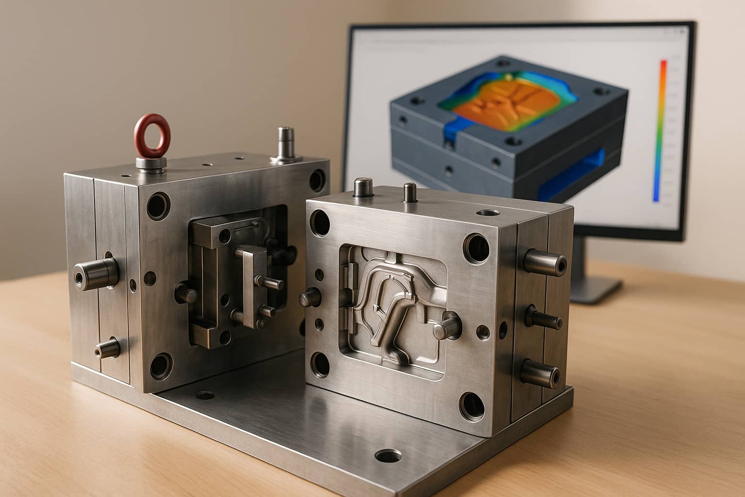
u Mold Structure: Complex cores, narrow runners, and the location of the venting system all directly affect the injection speed setting.
Interactions of Other Process Parameters:
u Mold Temperature: Higher mold temperatures result in slower melt cooling, allowing for a reduction in injection speed; lower mold temperatures necessitate high speeds to complete filling before solidification.
u Melt Temperature: Higher melt temperatures lead to lower viscosity and easier flow, reducing the need for high speeds; lower melt temperatures require high speeds and shear heat to assist in filling.
Reposted from:https://mp.weixin.qq.com/s/28uHTL4TklW-HAXwI0spmg