


Rapid CNC Machining: Professional Terminology
Category 1: Core Concepts & Philosophies
|
Term |
Definition & Context |
|
Rapid CNC Machining |
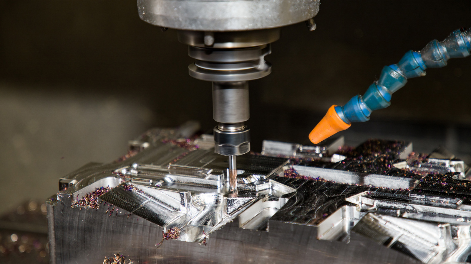
The use of CNC milling and turning
processes, optimized for maximum speed, to produce prototypes, tooling, and low-volume
parts with very short lead times. |
|
Lead Time |
The total time from order placement to part
delivery. Minimizing this is the primary goal of rapid CNC. |
|
Digital Manufacturing |
An overarching term for manufacturing
processes driven directly by digital CAD data, with minimal human
intervention. Rapid CNC is a key part of this. |
|
The practice of designing parts to simplify
the machining process, reduce costs, and decrease production time. Critical
for rapid turnaround. |
|
|
Design for Machining (DFM) |
A subset of DFM focused specifically on
optimizing part design for CNC machining (e.g., avoiding deep pockets, using
standard radii). |
|
Agile Manufacturing |
A methodology that emphasizes flexibility
and rapid response to change. Rapid CNC is a key enabler. |
Category 2: The Digital Workflow (CAD/CAM)
|
Term |
Definition & Context |
|
CAD (Computer-Aided Design) |
Software used to create the 3D model of the
part (e.g., SolidWorks, Fusion 360, CATIA). The process starts here. |
|
CAM (Computer-Aided Manufacturing) |
Software that converts the 3D CAD model
into a set of instructions (G-code) that the CNC machine can execute. |
|
G-code |
The programming language that controls the
CNC machine. It dictates tool movement, spindle speed, feed rate, and other
functions. |
|
Post-Processor |
A software translator within the CAM system
that converts the generic toolpaths into specific G-code for a particular
brand and model of CNC machine. |
|
Toolpath |
The calculated path that a cutting tool
will follow to machine the part. Efficient toolpath strategies are crucial
for speed. |
|
The engineer who operates CAM software to
create efficient, error-free toolpaths and G-code for the machine. |
Category 3: Machining Strategies & Toolpaths
|
Term |
Definition & Context |
|
3-Axis Machining |
The most common type, where the cutting
tool can move in three linear directions (X, Y, Z). Ideal for parts without
complex undercuts. |
|
5-Axis Machining |
A method where the tool can move in three
linear axes and the workpiece can rotate on two additional axes (A and B).
This allows for complex parts to be completed in a single setup, drastically
reducing lead time. |
|
Simultaneous 5-Axis |
The tool can move along all five axes at
the same time, enabling the machining of highly complex, organic shapes. |
|
High-Speed Machining (HSM) |
A strategy using high spindle speeds, fast
feed rates, and shallow depths of cut to maintain a constant tool load,
remove material quickly, and achieve a better surface finish. |
|
High-Efficiency Machining (HEM) |
Also known as Adaptive Clearingor Dynamic Milling, this is a roughing strategy that
uses a toolpath that maintains a constant chip load and radial engagement,
allowing for much higher feed rates and deeper axial cuts to remove material
rapidly. |
|
Rest Machining |
A CAM feature that identifies areas where
material remains from a previous operation (e.g., after a large tool roughs
out an area), allowing a smaller tool to machine only the remaining stock. |
|
Roughing |
The initial machining step aimed at
removing the bulk of the material as quickly as possible, without regard for
final surface finish. |
|
Finishing |
The final machining step that cuts the part
to its exact dimensions and achieves the desired surface finish. |
|
Contouring |
A toolpath that follows the contours of the
part geometry. |
Category 4: Machine Components & Setup
|
Term |
Definition & Context |
|
CNC Mill / Machining Center |
The machine tool itself, typically
classified by the number of axes (3-axis, 5-axis). |
|
CNC Lathe / Turning Center |
A machine for producing cylindrical parts
by rotating the workpiece against a stationary cutting tool. |
|
Mill-Turn Center |
A hybrid machine that combines milling and
turning capabilities, allowing complete machining of complex parts in a
single setup. |
|
Spindle |
The part of the machine that rotates the
cutting tool. Spindle
Speed is measured in RPM (Revolutions Per Minute). |
|
Workholding |
The method of securing the workpiece to the
machine table. Rapid setups use quick-change systems. |
|
Vise |
A common workholding device that uses jaws
to clamp the part. |
|
Fixture |
A custom workholding device designed for a
specific part to hold it in a precise orientation. |
|
Chuck |
The workholding device on a lathe that
grips the rotating workpiece. |
|
Tool Holder |
The device that connects the cutting tool
to the machine spindle (e.g., Collet Chuck, End Mill
Holder). |
|
Automatic Tool Changer (ATC) |
A magazine of tools that allows the machine
to automatically change cutting tools during a program, enabling
uninterrupted machining. |
|
Pallet Changer |
A system with two or more pallets (tables).
While the machine is machining a part on one pallet, the operator can set up
the next part on another, eliminating machine downtime. |
|
Probe |
A touch-trigger sensor used to
automatically find the exact position of the workpiece (workpiece
probing) or to measure tool length (tool probe), automating
setup and in-process inspection. |
Category 5: Cutting Tools & Parameters
|
Term |
Definition & Context |
|
End Mill |
The most common cutting tool for milling,
available in many types (flat, ball-nose, corner-radius). |
|
Face Mill |
A large-diameter tool used for quickly
creating a flat surface. |
|
Insert |
A removable, indexable cutting tip, usually
made of carbide, that is held in a tool holder. When one edge dulls, it can
be rotated to a fresh edge. |
|
Feed Rate |
The speed at the cutting tool moves through
the material, measured in inches per minute (IPM) or millimeters per minute
(mm/min). |
|
Spindle Speed (RPM) |
The rotational speed of the spindle and
cutting tool. |
|
Cutting Speed (SFM / m/min) |
The surface speed of the tool at the
cutting edge, measured in Surface Feet per Minute (SFM) or meters per minute.
It is a key factor in determining RPM. |
|
Depth of Cut |
The amount of material removed in a single
pass, either axially (stepdown) or radially (stepover). |
|
Chip Load |
The thickness of the material removed by
each cutting edge of the tool per revolution. Optimizing chip load is
critical for tool life and efficiency. |
|
Coolant / Lubricant |
A fluid used to cool the tool and workpiece
and to flush away chips. Flood coolant is common,
while Minimum
Quantity Lubrication (MQL) is used for a near-dry process. |
Category 6: Quality & Metrology
|
Term |
Definition & Context |
|
First Article Inspection (FAI) |
The comprehensive verification of the first
part produced to ensure it meets all design specifications. |
|
In-Process Inspection |
Quality checks performed during the
machining process to catch errors early. |
|
Coordinate Measuring Machine (CMM) |
A precision instrument that uses a probe to
measure the geometry of a physical part and compare it to the CAD model. |
|
Digital Calipers / Micrometers |
Handheld measuring tools for quick
dimensional checks. |
|
Surface Finish |
The texture of the machined surface,
measured by roughness (Ra, Rz). |
|
Tolerance |
The permissible limit of variation in a
physical dimension. Tight tolerances increase machining time and cost. |
|
Geometric Dimensioning & Tolerancing
(GD&T) |
A symbolic language used on engineering
drawings to define the allowable variation in form, orientation, and location
of part features. |