



Tapping and Threading: What Is a Tapped Hole and How Does It Differ From a Threaded Hole?


Tapping is used to make internal threads with a tap. Threading is the broader term and includes processes such as tapping, thread milling, and thread inserts. On a CNC-machined part, the choice affects tool access, hole depth, thread quality, and production cost.
A tapped hole can look correct in CAD and still cause problems during machining or assembly. Blind-hole depth may leave too little room for chips. A difficult material can increase cutting load and tap-breakage risk. A drawing may specify the thread correctly but omit the depth or tolerance needed for inspection.
The decisions below focus on how to design, manufacture, specify, and inspect reliable threaded holes for CNC machining.
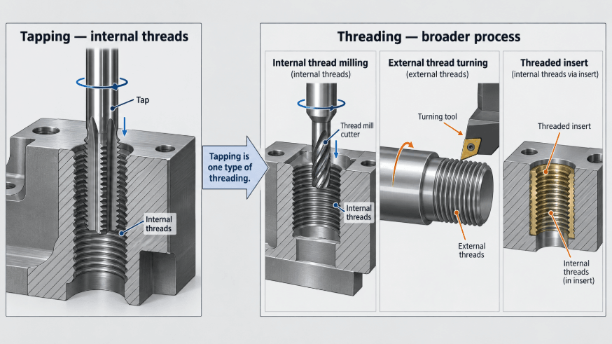
Figure 1: Tapping vs. Threading concept diagram
What Is the Difference Between Tapping and Threading?
Tapping is one method of creating an internal thread, while threading describes the wider manufacturing operation. A tapped hole is therefore a type of threaded hole. Internal threads can be produced by tapping, thread milling, or other methods depending on the material, geometry, thread size, depth, and production requirements.
| Term | What it means | Typical CNC application |
|---|---|---|
| Tapping | Cutting or forming internal threads with a tap | Standard threaded holes in common production materials |
| Threading | General term for producing a thread | Tapping, thread milling, or other threading methods |
| Tapped hole | An internal threaded hole made with a tap | Fastener holes, mounting points, assembly interfaces |
| Threaded hole | Any hole containing internal threads | Features made by tapping, thread milling, or inserts |
The distinction matters when discussing manufacturing requirements. If a drawing simply calls for a threaded hole, the manufacturer still needs to determine how the thread should be produced. A standard aluminum part with several identical holes may be well suited to tapping. A difficult material, unusual thread, or geometry requiring greater flexibility may favor thread milling.
All tapped holes are threaded holes, but not all threaded holes are tapped holes.
How Are Tapped Holes Made in CNC Machining?
A typical CNC tapped hole starts with drilling the correct pilot hole, followed by forming the internal thread with a tap. The machining sequence must account for hole diameter, thread pitch, material, thread depth, chip evacuation, and the available space below the finished thread.
A typical drill-and-tap sequence is:
- Drill the pilot hole to the diameter required for the selected thread.
- Prepare the hole entrance if a chamfer or countersink is required.
- Tap the hole using the specified pitch and thread form.
- Control thread depth, especially in blind holes.
- Remove chips and cutting fluid from the feature.
- Inspect the finished thread and its relationship to the mating geometry.
For blind holes, the machining sequence becomes more sensitive because the tap must enter and exit the material while chips have limited space to escape. If the available bottom clearance is too small, chips can pack into the hole, increasing torque and cutting resistance. That added load can damage the thread or, in severe cases, break the tap inside the part.
Taper, Plug, and Bottoming Taps
Tap geometry also affects how a thread is produced, particularly in blind holes.
| Tap type | Typical characteristic | Engineering consideration |
|---|---|---|
| Taper tap | Longer chamfer and gradual thread engagement | Useful for easier starting and lower initial cutting load |
| Plug tap | Moderate chamfer | General-purpose choice for many tapped holes |
| Bottoming tap | Short chamfer with threads extending closer to the end | Useful when deeper usable threads are required in blind holes |
Cutting taps remove material to create the thread. Form taps instead displace material and form the thread profile without producing conventional cutting chips. Form tapping can be useful in suitable ductile materials, but the required hole size and material behavior differ from those used for cutting taps.
Select the tap according to the material, hole geometry, and required thread depth—not simply the smallest available tool.
Tapping vs. Thread Milling: Which CNC Threading Method Is Better?
Tapping is usually efficient for standard internal threads, while thread milling offers greater flexibility for difficult materials, larger diameters, unusual threads, and some challenging geometries.
| Factor | Tapping | Thread milling |
|---|---|---|
| Best for | Standard internal threads and repeated holes | Difficult materials, larger threads, special threads, flexible production |
| Tooling | Dedicated tap for the thread | Thread mill can cover a range of applications depending on tooling |
| Production speed | Generally fast for repeated standard holes | Usually slower per hole |
| Blind holes | Requires careful chip evacuation and bottom clearance | Can offer more control over thread depth and chip evacuation |
| Material considerations | Cutting load and tap breakage can become concerns | Often useful where tapping torque is difficult to control |
| Thread flexibility | More limited by dedicated tap geometry | Greater flexibility in diameter, pitch, and thread strategy |
| Tool failure | Broken tap can be difficult to remove | Tool breakage is generally easier to manage inside an open machining process |
For a production part with many identical M6 or M8 holes in aluminum, tapping may be the straightforward choice. For a titanium component with difficult internal geometry, thread milling may deserve evaluation even if it adds machining time.
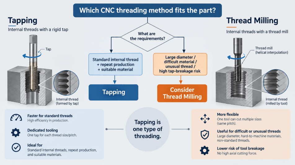
Figure 2: Tapping vs. thread milling decision diagram
A manufacturer should evaluate the material, thread size, thread depth, hole type, quantity, and required repeatability together before selecting the threading process.
Tapped-Hole Design for CNC Machining
A reliable tapped hole needs enough material around the thread, sufficient hole depth, practical tool access, and enough clearance below the finished thread. Thread diameter alone does not determine whether a hole is manufacturable. Blind-hole geometry, wall thickness, edge distance, and the relationship between the hole and mating components can all affect the result.
Blind Holes vs. Through Holes
| Feature | Through hole | Blind hole |
|---|---|---|
| Chip evacuation | Generally easier | More difficult |
| Thread depth control | Relatively straightforward | Requires additional bottom clearance |
| Tool access | Tool can pass through | Tool must stop within the part |
| Bottom geometry | No closed bottom | Drill point and unthreaded clearance matter |
| Typical risk | Edge breakout or insufficient material | Chip packing, torque increase, tap breakage |
Blind holes deserve particular attention. The drill creates a point at the bottom unless a flat-bottom operation is used, so the total drilled depth is normally greater than the required full-thread depth.
As a practical starting reference, some CNC design guidance uses approximately 0.5× the nominal thread diameter of additional unthreaded clearance below the required full thread depth. This is a reference for planning, not a universal formula. The actual clearance depends on the tool, tap geometry, material, thread depth, and machining strategy.
For example, if an M8 thread needs 10 mm of full thread depth, simply specifying a 10 mm-deep drilled hole may leave insufficient room for the tap and chips. The manufacturer may need additional depth below the functional thread.
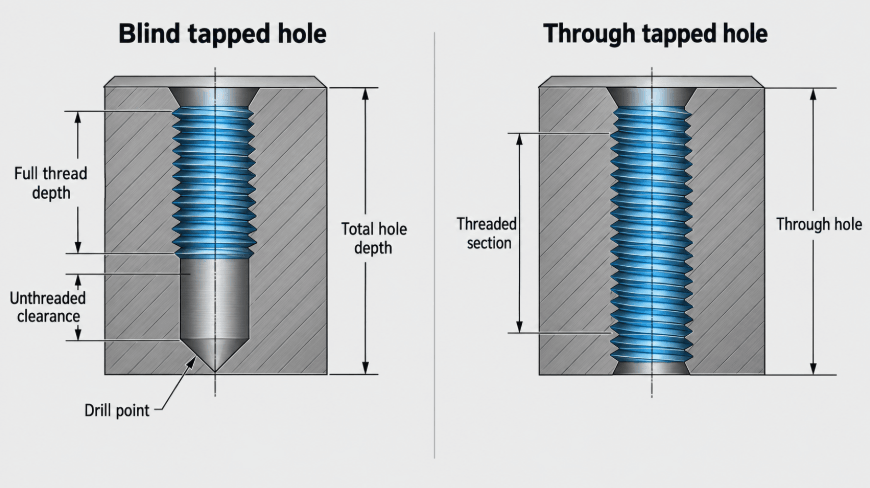
Figure 3: Tapped hole cross-section showing total hole depth, full thread depth, and bottom clearance
How Much Thread Depth Is Enough?
More thread depth does not automatically make a joint stronger. Once sufficient thread engagement is available for the required load, additional thread depth may add machining time and cost without providing a proportional increase in holding strength.
A common starting reference is around 2× the nominal thread diameter for thread engagement in many metal applications, but this should not be treated as a design formula. Required engagement depends on material strength, fastener material, load direction, thread quality, joint design, and whether the threaded hole will be assembled repeatedly.
For a stronger material such as steel, the required engagement may differ from a softer material such as aluminum. If the joint is highly loaded or frequently assembled and disassembled, the design may also need a larger engagement length or a threaded insert.
Edge Distance, Wall Thickness, and Tool Access
The hole also needs enough surrounding material to maintain structural integrity. A tapped hole placed too close to an edge can weaken the surrounding wall or cause breakout during drilling and tapping.
Check:
- Distance from the hole to nearby edges
- Remaining wall thickness
- Interference with adjacent features
- Drill and tap access
- Tool orientation
- Required thread depth
- Countersink or chamfer requirements
- Clearance for the mating fastener
For complex components, the threaded feature should be evaluated together with the surrounding geometry rather than treated as an isolated hole.
Tapped-Hole Callouts on Engineering Drawings
A tapped-hole callout should define the thread standard, nominal size, pitch, tolerance class where applicable, and whether the thread is through or blind. If the hole is blind, the required thread depth should be stated clearly so the manufacturer can distinguish functional thread depth from total drilled depth.
Typical metric examples include:
- M8 × 1.25 – 6H THRU
- M6 × 1.0 – 6H × 10 mm DEEP
Typical inch examples include:
- 1/4-20 UNC-2B THRU
- #10-32 UNF-2B × 0.25 in DEEP
The callout should match the actual design requirement. Avoid specifying an unusually fine pitch or nonstandard thread unless the assembly requires it, because specialized tooling can increase manufacturing complexity.
For production parts, also identify any requirements that affect assembly, such as:
- Thread class or tolerance
- Full thread depth
- Minimum usable thread depth
- Countersink or chamfer
- Positional tolerance
- Perpendicularity
- Surface requirements at the mating interface
A correct thread callout tells the manufacturer what thread to make. GD&T and feature controls may still be required to define where that thread must be and how it must relate to the rest of the part.
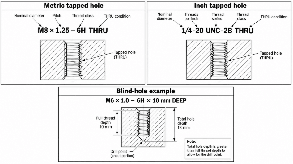
Figure 4: Metric and inch tapped-hole callout drawing with THRU and blind-hole examples
How Does Material Affect Tapped Hole Design?
Material changes the cutting load, thread strength, chip behavior, and long-term performance of a tapped hole. The same thread specification can behave differently in aluminum, stainless steel, titanium, engineering plastics, or composite materials, so material selection should be considered alongside thread geometry and assembly requirements.
| Material | Typical risk | Process / design response |
|---|---|---|
| Aluminum | Lower thread strength than many steels; repeated assembly can wear the threads | Provide appropriate engagement; consider inserts for frequent assembly or higher loads |
| Stainless steel | Higher cutting resistance and potential work hardening | Control cutting conditions and tooling; avoid unnecessary dwell or repeated tool engagement |
| Titanium | Heat generation, cutting resistance, and tool-wear concerns | Evaluate tapping versus thread milling and control machining conditions carefully |
| Engineering plastics | Thread deformation, wear, or creep under load | Consider larger engagement, suitable thread geometry, or inserts depending on the application |
| FR-4 / composites | Abrasive behavior and risk of damaging the surrounding laminate | Control machining and consider threaded inserts for stable assembly interfaces |
For example, Mastars has machined complex curved FR-4 structural components with press-fit brass threaded inserts where the inserts provided stable and repeatable threaded interfaces.
The important point is that the thread specification alone does not determine joint performance. The manufacturer should consider the material’s strength, machinability, thermal behavior, and expected assembly cycle.
How Are Tapped and Threaded Holes Inspected?
Thread inspection checks whether the finished feature has the required thread form and size, but assembly-critical holes may also require positional and geometric inspection. A thread can pass a basic size check and still cause an assembly problem if the hole is misplaced, angled incorrectly, or poorly related to another mating feature.
Common inspection methods include:
- Go / No-Go thread gauges for checking functional thread limits
- Dimensional inspection for hole diameter, depth, and related features
- CMM inspection for hole location and geometric relationships
- First Article Inspection (FAI) for initial production validation
- IPQC / FQC for in-process and final inspection
For a threaded hole that only provides clamp force, thread size may be the primary concern. If the hole locates a mating component, however, thread size and thread location are separate requirements. Position, perpendicularity, and the relationship between the threaded hole and adjacent datum features may be just as important as whether the fastener enters correctly.
Mastars supports dimensional inspection using equipment such as a HEXAGON Global Silver CMM, together with FAI, IPQC, and FQC controls for applicable projects.
Tapped-Hole DFM Checklist
Before machining, review the threaded feature as part of the complete assembly rather than checking only the hole diameter and pitch. A short DFM review can identify blind-hole depth problems, unsuitable thread standards, insufficient edge distance, difficult tool access, or inspection requirements before they become machining or assembly problems.
| DFM check | What to verify |
|---|---|
| Thread standard | Metric or inch, nominal diameter, pitch, class |
| Hole diameter | Correct pilot-hole size for the selected thread |
| Thread depth | Functional depth versus total drilled depth |
| Hole type | Through or blind |
| Bottom clearance | Enough room for the tap and chips |
| Material | Machinability, thread strength, work hardening, wear |
| Edge distance | Adequate surrounding material |
| Tool access | Straight and sufficient access for drilling and tapping |
| Assembly | Fastener clearance, engagement, repeated assembly requirements |
| Inspection | Thread gauge, location, depth, GD&T, CMM requirements |
This matters when several precision features interact. In a precision transmission assembly, gears, shafts, splines, and mounting interfaces must work together; checking each feature independently can miss assembly-level problems.
For parts with multiple fixing points, the same principle applies. Mastars has also applied engineering review to PC+ABS trim substrates where key holes, screw bosses, and fixing points were controlled within specified dimensional requirements.
What Should You Send a Manufacturer for a Threaded-Part Quote?
A manufacturer can usually start evaluating a threaded part with a CAD model, drawing, material requirement, quantity, and the critical thread specifications. The more clearly you identify functional threads and assembly requirements, the easier it is to select a suitable machining strategy and identify risks before production.
For an RFQ, provide:
- 3D CAD model
- 2D engineering drawing, if available
- Material and grade
- Quantity or expected production volume
- Thread standards and callouts
- Critical dimensions and GD&T
- Surface finish requirements
- Functional or cosmetic requirements
- Target application or assembly information, when relevant
Rough information is fine to start. If the drawing is still being developed, identify the threads that are functionally important and explain what the part needs to assemble with. That gives the manufacturer useful context before the design is fully released.
Have a CNC-machined part with tapped or threaded holes?
Send your CAD file and drawing for review. Include any critical dimensions, thread requirements, material specifications, or surface requirements that could affect the build.
Conclusion
A reliable tapped hole is designed around the joint it must perform in, not simply around a thread size. The material, engagement length, blind-hole clearance, hole position, fastener, assembly cycle, and inspection requirements all contribute to the final result.
For standard holes in suitable materials, tapping may be the fastest and simplest approach. Thread milling or threaded inserts may be more appropriate when material behavior, geometry, repeated assembly, or production risk changes the equation.
The best manufacturing decision is made before the tool enters the part.
FAQ
Is a tapped hole the same as a threaded hole?
Not exactly. A tapped hole is a threaded hole made using a tap. “Threaded hole” is the broader term and can include holes produced by tapping, thread milling, or threaded inserts.
Is tapping better than thread milling?
It depends. Tapping is generally efficient for standard, repeated threads. Thread milling can be more suitable for difficult materials, unusual threads, larger diameters, or applications where greater control over the threading operation is useful.
How deep should a tapped hole be?
Only as deep as the assembly requires, with enough additional space for the manufacturing process. Around 2× the nominal diameter is a useful starting reference for thread engagement in many metal applications, but it is not a universal formula. Material strength, joint load, fastener size, and assembly requirements can change the required depth.
How much extra depth does a blind tapped hole need?
The total hole depth normally needs to exceed the required full-thread depth. A starting reference of roughly 0.5× the nominal diameter for additional unthreaded clearance is sometimes used, but the actual requirement depends on the tap, material, hole depth, and chip-evacuation strategy.
Can aluminum parts be tapped directly?
Yes. Aluminum is commonly tapped directly when the thread has sufficient engagement and the joint does not require an unusually high number of assembly cycles. For highly loaded or repeatedly assembled connections, a threaded insert may provide a more durable interface.
Can plastics and composites be tapped?
Yes, but the design needs to account for material behavior. Plastics can deform or wear under repeated loading, while composites such as FR-4 can require different machining and reinforcement strategies. Inserts are often worth evaluating when long-term thread stability matters.
What information should I provide for a tapped-hole quote?
Provide the CAD model, drawing if available, material, quantity, thread callouts, critical tolerances, and surface requirements. If some details are not finalized, rough information is still useful. Identifying the mating fastener or assembly function can also help determine whether thread depth, location, or an insert needs special attention.
Hot Articles
Hot Tags
Stay Connected!


Manufacturing on Demand
Please fill in the following information to obtain plan details (information is confidential and not disclosed publicly), we will contact you within 24 hours, please keep your phone available!
Upload a 3D/2D model to see instant pricing, lead time, and DFM feedback.