

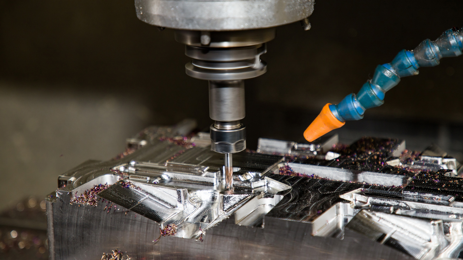

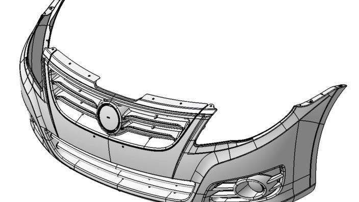
Plastic extrusion molding is one of the most widely used and fundamental technologies in the modern plastics processing industry. It is a highly efficient, continuous production process that transforms solid plastic raw materials (pellets or powder) into a molten state through heating, pressurization, and shear action within a machine. This melt is then forced through a die of a specific shape, and finally cooled and shaped into a continuous profile with a constant cross-section. This article aims to provide an in-depth analysis of plastic extrusion molding, detailing its core principles, system components, step-by-step operational procedures, and focusing specifically on the key operational challenges and solutions during production. Finally, it will explore the future development trends of this technology.
1.1 Core Principle
The essence of extrusion molding is a complex physical process, primarily consisting of the stages of solid conveying, melting/plasticating, melt conveying, shaping, and cooling. Its driving force comes from the rotation of the screw, the core component of the extruder. The screw rotates within a heated barrel, transporting the solid plastic forward through friction and viscous drag. During this process, the plastic absorbs energy from external heaters on the barrel and from the immense internal heat generated by screw shear, gradually melting into a homogeneous viscous fluid. Finally, this molten plastic is pushed by the screw at high pressure and speed through the die, forming the desired shape.
1.2 Main Characteristics
Continuous Production: Once started, it can theoretically produce continuously indefinitely, offering extremely high efficiency.
High Production Efficiency: Ideal for the manufacture of large-scale, long-length products such as pipes, sheets, and films.
Wide Range of Applications: By changing dies and auxiliary equipment, a variety of products with different cross-sectional shapes can be produced, such as tubes, rods, sheets, films, filaments, wire coatings, profiles, and for tasks like plastic mixing, plasticating, and pelletizing.
Versatility: One extruder, equipped with different auxiliary equipment, can perform multiple processing tasks.
1.3 Main Application Products
Extruded products are ubiquitous, permeating all aspects of daily life:
Pipes: Water supply/drainage pipes, gas pipes, electrical conduits.
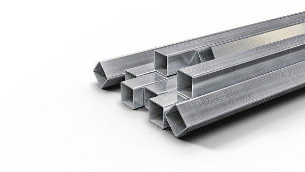
Profiles: Window and door profiles, decorative trims, plastic-steel profiles.
Sheets/Films/Films: Signage boards, food packaging trays, industrial sheets, agricultural film, packaging film.
Filaments/Ropes/Straps: Filaments for woven bags, ropes, strapping bands.
Coating: Insulation and sheathing for wires and cables.
Parisons for Blow Molding: Providing the parison for blow molding (e.g., bottles).
Plastic Compounding and Pelletizing: Melting and blending mixed raw materials via an extruder to pelletize new composite materials.
A complete extrusion production line consists of three main parts: the Main Unit (extruder), the Auxiliary Equipment (sizing, cooling, haul-off, cutting devices), and the Control System.
2.1 Main Unit - The Extruder
The extruder is the heart of the system, responsible for plasticating and conveying the plastic. The most common type is the single-screw extruder.
a. Feed System:
Hopper: Used for storing and supplying plastic raw materials. Often equipped with a dryer to prevent moisture in the raw material from vaporizing at high temperatures, causing bubbles or silver streaks in the product.
Feed Throat: The first section of the barrel where material enters from the hopper.
b. Extrusion System:
Barrel: A sturdy metal cylinder, internally precision-machined and hardened to withstand high temperatures and pressures. Externally, it is equipped with zone-controlled heaters (e.g., resistance heaters) and cooling devices (e.g., air or water cooling).
Screw: The soul of the extruder. Its design directly determines the quality of plasticization and output. A typical screw is divided into three functional zones:
Feed Zone: Conveys and preheats solid plastic from the hopper.
Compression Zone (Plasticating Zone): The channel depth gradually decreases, compressing the plastic, removing air, and melting the plastic via intense shear heat and external barrel heating.
Metering Zone (Melt Zone): The channel depth is shallowest and constant. Its main function is to homogenize the melt temperature and composition further and deliver the melt to the die at a constant, uniform pressure and flow rate.
Screw Design Variants: For plastics with different characteristics (e.g., PVC, PE, PP, PC), there are specialized designs like gradual compression, sudden compression, barrier screws, and mixing screws to optimize plasticization.
c. Drive System:
Includes the motor, gearbox, and thrust bearing. It provides stable, adjustable speed rotation to the screw and withstands enormous axial thrust.
d. Heating/Cooling System:
Ensures the plastic is plasticated within the required temperature range. Heaters provide the initial heat source, while cooling systems (fans or water jackets) prevent material overheating and degradation when shear heat is excessive, enabling precise temperature control.
2.2 Auxiliary Equipment System
The auxiliary equipment determines the final product's geometry, appearance, and properties.
a. Die and Tooling:
This is the key component that imparts the cross-sectional shape to the product. The molten plastic is "shaped" here. Its flow channel design is critical, ensuring uniform melt flow velocity to avoid stagnation or degradation. Design must consider melt rheology (e.g., shear thinning) and die swell.
b. Sizing Device:
The hot profile exiting the die is molten and must be sized immediately. Sizing methods include:
Vacuum Sizing: Most common for profiles and pipes. The profile is pulled into a sizing die (sizing sleeve), where its outer wall adheres tightly to the die's inner wall under vacuum suction, cooled and hardened by cooling water.
Pressure Sizing: Mainly for pipes, where compressed air is introduced inside the tube, pressing the outer wall against the sizing sleeve for cooling.
Calibrator: A combination of cooling and sizing devices ensuring the profile gradually reaches precise dimensions during cooling.
c. Cooling Device:
After sizing, the product needs further cooling to gain sufficient strength. Typically done using cooling tanks (immersion) or spray tanks. Cooling must be slow and uniform to avoid internal stress concentration, warpage, or deformation.
d. Haul-off (Puller) Device:
Provides stable, continuous pulling force, evenly drawing the sized profile from the die. The haul-off speed must be strictly synchronized with the extrusion speed. Excessive speed thins or breaks the product; insufficient speed causes material buildup at the die. Common equipment includes caterpillar haul-offs and roller haul-offs.
e. Cutting Device:
Cuts the continuously extruded product to the required length. Types include synchronized rotary saws (for rigid products) and guillotine cutters (for soft products).
2.3 Control System
Modern extrusion lines use advanced computer-integrated control to monitor and adjust process parameters, including:
Temperature Control: Precise PID control of temperatures in each barrel zone and the die.
Speed Control: Precise control of screw speed and haul-off speed.
Pressure Monitoring: Melt pressure sensors at the die head monitor plasticating stability and prevent overpressure damage.
Sequential Control: Ensures synchronized operation of auxiliary equipment like the haul-off and cutter with the main unit.
Step 1: Preparation
Raw Material Pre-treatment: Depending on the material, drying may be required (for hygroscopic materials like PET, PC, Nylon) or pre-mixing with color masterbatch and additives.
Equipment Check and Heating: Check all equipment components. Set and activate heaters for each barrel and die zone according to the process specification. Heat to set temperatures and soak (typically 30-60 mins) for temperature uniformity.
Install Die and Auxiliaries: Install and align the die, sizing die, cooling tank, haul-off, and cutter.
Step 2: Start-up and Feeding
Start Screw at Low Speed: After reaching and stabilizing at set temperatures, start the screw at the lowest RPM.
Feed Material Gradually: Add a small amount of pure material to "purge" the machine, cleaning the screw and barrel of contaminants or degraded material. Then add the production material.
Observe Melt Discharge: Observe the melt exiting the die. Once the material is plasticated uniformly and color is consistent, the plasticating process is stable.
Step 3: Threading and Sizing
Manual Guidance: Carefully guide the soft extrudate into the sizing device. This step requires operator skill to prevent twisting or jamming.
Start Auxiliaries: Once the profile passes through the sizer, immediately start the vacuum pump, cooling water, and haul-off.
Adjust Alignment: Fine-tune the die or sizer position to ensure product straightness.
Step 4: Continuous Production and Process Optimization
Speed Matching: Gradually increase screw speed to the target, simultaneously adjusting haul-off speed to achieve dynamic balance. Measure product dimensions and fine-tune haul-off speed until dimensions are qualified.
Stable Operation: Once the line is stable, operators periodically check and record key parameters (temperature, pressure, speed) and sample products for appearance and dimensions.
Step 5: Shutdown and Purge
Stop Feeding: At the end of production, first stop feeding the hopper.
Purge the Barrel: Continue running the extruder until no more material exits the die. For heat-sensitive materials, purge with a more stable material to prevent degradation.
Cooldown and Stop: Gradually reduce heater temperatures. After cooling below a certain point, stop the screw and all auxiliaries. Turn off power and cooling water.
Extrusion seems straightforward, but producing high-quality products stably requires overcoming a series of complex process challenges.
Challenge 1: Melt Fracture and Sharkskin
Phenomenon: When the extrusion rate exceeds a critical value, the product surface becomes rough, showing regular spiral or bamboo-like cracks or fine ripples. This severely affects appearance and mechanical properties.
Mechanism:
Melt Fracture: Stems from elastic instability of the melt within the die flow channel. High shear stress causes periodic stick-slip flow.
Sharkskin: Occurs mainly at the die exit, due to stick-slip between the melt surface and the die lip.
Solutions:
Reduce Extrusion Speed: Most direct method, but reduces output.
Increase Melt Temperature: Reduces viscosity and elasticity, raising the critical shear rate.
Modify Die Design: Increase die entry angle, lengthen the land, use streamlined flow channels to reduce resistance.
Use Processing Aids: Additives can form a lubricating layer at the melt-metal interface.
Challenge 2: Die Swell and Die Design
Phenomenon: The extrudate diameter is greater than the die diameter after exiting. This is caused by elastic recovery of polymer chains oriented by shear within the die.
Mechanism: Polymer elastic memory effect.
Impact and Solutions:
Impact: Die swell is inevitable but difficult to predict, posing a major challenge for die design. Poor design leads to incorrect dimensions, high internal stress, and warpage.
Solutions:
Empirical Die Design: Based on deep understanding of material rheology, using CFD simulation and experimental data to design non-circular flow channels that "pre-compensate" for swell.
Adjust Process Parameters: Increasing temperature or decreasing speed can reduce die swell.
Lengthen Die Land: Allows more time for molecular relaxation inside the die, reducing orientation.
Challenge 3: Thermal Degradation and Stability
Phenomenon: Prolonged residence time or local overheating in the barrel causes chain scission/crosslinking, resulting in yellowing, black specs, bubbles, odor, and severe property loss.
Mechanism: Overheating from high temperatures and shear, contaminants acting as degradation sites.
Solutions:
Strict Temperature Control: Precise setting and monitoring of zone temperatures. Proper heater power and effective cooling.
Optimize Screw Design: Use screws with gentler shear to improve efficiency and reduce residence time.
Thorough Cleaning: Regular, thorough purging, especially during material/color changes.
Use Stabilizers: Essential for sensitive polymers.
Challenge 4: Cooling and Internal Stresses
Phenomenon: Warping, bending, sink marks, or dimensional instability after cooling due to uneven or rapid cooling causing internal stress release.
Mechanism: Plastic shrinks upon solidification. If the surface cools and hardens first while the interior cools and shrinks later, it creates tensile stresses on the surface.
Solutions:
Uniform Cooling: Ensure even water flow in cooling tanks or use spray cooling.
Gradual Cooling: Use multi-stage cooling with decreasing water temperatures for slow, uniform cooling.
Optimize Sizing Die: Ensure proper cooling channel layout in the sizing die.
Annealing: For high-precision parts, an annealing step relieves internal stresses.
Challenge 5: Screw and Barrel Wear
Phenomenon: Gradual output decrease, poor plastication, melt pressure fluctuations due to increased clearance from wear.
Mechanism: Abrasion from fillers and corrosion from certain plastics.
Solutions:
Wear-Resistant Materials: Use nitrided screws, bimetallic barrels.
Proper Clearance Control: Monitor and maintain screw/barrel clearance.
Filler Control: Consider filler particle size and hardness.
Challenge 6: Process Stability and Control
Phenomenon: Minor but unacceptable dimensional variations even with constant setpoints.
Mechanism: Raw material variability, ambient temperature changes, equipment drift.
Solutions:
Advanced Closed-Loop Control: Use adaptive PID control with online gauges for real-time feedback to screw speed or haul-off.
Material Homogenization: Pre-blending and pre-plasticating ensure batch consistency.
High Precision and Intelligence: IIoT, big data analytics for predictive maintenance, self-optimizing parameters, and full digital management.
High Efficiency and Energy Saving: Low-energy drives, high-torque systems, and energy-saving technologies like physical foaming.
New Material Processing: Adapting to biodegradable plastics, high-performance polymers, and thermoplastic composites.
Miniaturization and Scaling Up: Trends towards micro-scale extrusion and very large-diameter pipe extrusion.
Multi-Layer Coextrusion: Using multiple extruders with one die to produce multi-layer films/sheets for high-barrier, high-strength applications.
Plastic extrusion molding is a comprehensive industrial technology integrating polymer science, mechanical engineering, rheology, thermodynamics, and automatic control. While the process appears linear and continuous, it involves complex internal physico-chemical changes and dynamic balances. A deep understanding of the mechanisms from solid conveying to final cooling is fundamental to mastering this technology. The core of successful production lies in accurately identifying and effectively solving the aforementioned operational challenges, finding the optimal balance between output, quality, and cost through optimized equipment, process parameters, and control systems. As new materials and technologies emerge, this classic process will continue to evolve towards greater efficiency, precision, intelligence, and sustainability, playing an increasingly vital role in the global economy.