



Molding Tooling: From Mold Design to Reliable Production


A part can look perfectly reasonable in CAD and still create problems once you try to mold it. Maybe a thick boss leaves a sink mark. A deep wall needs more draft than the original design allows. A gate ends up on a visible surface. Or the mold produces an acceptable first sample, but dimensional variation becomes difficult to control in production.
These problems do not always start with the molding machine or the material. Quite often, they start with decisions made during molding tooling.
The basic idea is simple: the part design defines what you want to make. The tooling determines how reliably you can make it. That is why tooling should be considered while the product is still being developed, not only after the design is frozen.
This guide looks at molding tooling from an engineering and production perspective: what the mold controls, which tooling decisions matter most, how to choose tooling for different production stages, what drives tooling cost, and what should be checked before a mold is released for production.
What Is Molding Tooling—and What Does It Actually Control?
In this article, molding tooling mainly refers to tooling used for injection molding plastic parts.
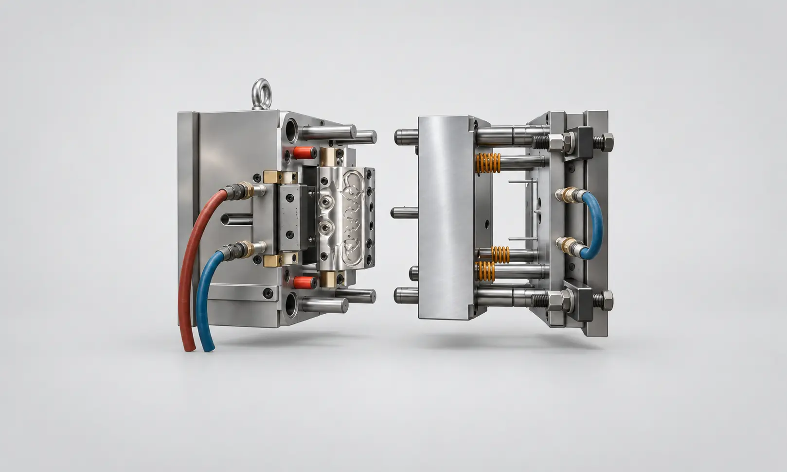
An injection mold is more than a cavity cut into steel or aluminum. It is a complete system that controls how plastic enters the mold, how it fills the cavity, how heat is removed, and how the finished part is ejected.
A typical injection mold includes:
- Core and cavity
- Runner and gate system
- Cooling channels
- Ejection system
- Guide and alignment components
- Slides or lifters for undercuts
- Inserts where required
Each component affects the others. A gate location can affect filling and weld lines. Cooling affects both cycle time and dimensional stability. Ejection affects part deformation and surface marks. The parting line can affect appearance as well as tooling complexity.
So when engineers review a mold, they are not simply asking whether the cavity can be machined. They are asking: Can this part be molded reliably as designed? If the answer is no, the next question should be: What is the simplest design or tooling change that removes the risk? That is where a good DFM review earns its value.
The Mold Systems That Matter Most
You do not need to understand every mold component to make a good tooling decision. But four systems deserve particular attention.
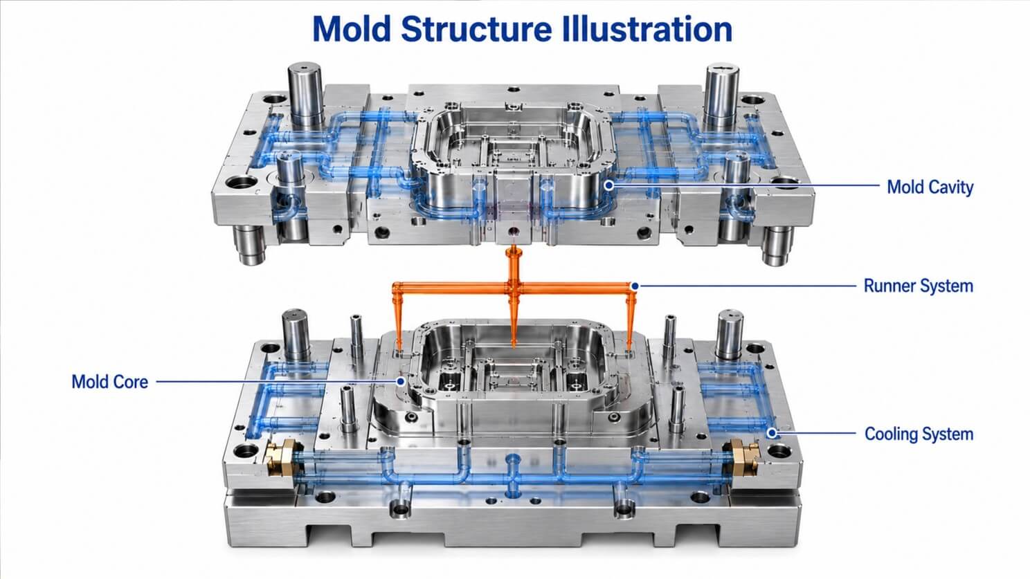
Core and cavity
The core and cavity form the main surfaces of the molded part. Their machining accuracy and alignment affect the dimensions of the part, especially when features on opposite sides have to work together.
A mold can hold individual dimensions well and still produce an assembly that does not fit properly. The problem may be the relationship between several features rather than any single dimension. This becomes more important for mechanisms, snap-fits, connectors, and other functional assemblies.
Runner and gate system
The runner carries molten plastic toward the cavity. The gate controls where the plastic enters the part. Gate location can affect filling behavior, weld-line position, packing, cosmetic appearance, material flow length, and local shrinkage.
There is no universal “best” gate location. A gate that is easy to machine may not be the best choice for the part. On a cosmetic housing, for example, the gate mark may be more important than the small tooling convenience of placing the gate in an accessible area.
Cooling system
Cooling controls how quickly heat leaves the molded part and the mold. It directly affects cycle time, but it also affects dimensional stability.
If one area of a part cools much faster than another, the different shrinkage behavior can contribute to warpage or dimensional variation. This is why cooling should be considered together with wall thickness and part geometry rather than treated as a separate mold-design task.
Ejection system
After filling and cooling, the part still needs to come out of the mold. Ejector pins, sleeves, lifters, and other mechanisms must release the part without causing excessive deformation or unwanted marks.
An ejector mark on an internal surface may be acceptable. The same mark on a visible cosmetic surface may not be. Ejection therefore needs to be planned around the actual part requirements.
How Mold Design Affects the Final Part
Many molding defects are visible only after the part has been molded. Their causes can start much earlier.
Wall thickness and material flow
Large changes in wall thickness can create differences in filling, cooling, and shrinkage. Depending on the geometry and material, this may lead to sink marks, warpage, uneven appearance, longer cooling time, or dimensional variation.
The answer is not always to make every wall the same thickness. Functional requirements may make that impossible. The better approach is to identify where thickness changes create a real molding risk and decide whether the geometry, material, gate, or cooling strategy needs adjustment.
Draft and ejection
A feature that looks fine in CAD may still be difficult to release from the mold. Insufficient draft can increase friction during ejection and lead to drag marks, deformation, or surface damage.
The required draft depends on factors such as material, surface texture, feature depth, and geometry. This is one of the reasons draft should be reviewed during DFM rather than after the mold has already been manufactured.
Ribs and bosses
Ribs provide stiffness. Bosses provide mounting or fastening points. Both are common and useful features. The problem comes when a feature creates a local thick section or makes cooling difficult.
For example, a thick boss connected directly to a relatively thin wall can increase the risk of sink marks. A small geometry change made during design review can be much cheaper than correcting the problem after tooling has been cut.
Parting lines and undercuts
Parting-line location affects part appearance, ejection, mold structure, flash risk, and tooling complexity. Undercuts may require slides, lifters, or inserts.
That added complexity is not automatically bad. If an undercut is essential to the product, it may be better to engineer the tooling around it than to compromise the product design just to simplify the mold. The important point is to understand the cost and manufacturing effect before the decision is locked in.
Tooling Decisions That Affect Production
Some tooling decisions influence far more than the mold itself.
| Tooling Decision | What It Can Affect | What to Review |
|---|---|---|
| Parting line | Appearance, ejection, flash, tooling complexity | Cosmetic surfaces, undercuts |
| Gate location | Filling, weld lines, packing, appearance | Flow path, wall thickness |
| Runner design | Filling balance, material usage | Cavity balance, pressure |
| Cooling layout | Cycle time, warpage, dimensional stability | Thick sections, temperature distribution |
| Ejection system | Part release, deformation, marks | Ejector position and force |
| Cavity count | Output, tooling investment, balance | Annual volume, cycle time |
| Tool material | Tool life, machining, cost | Resin, volume, surface requirements |
Gate location is a product decision too
A gate is not simply a place where plastic enters the mold. Its location can determine where weld lines appear, how the cavity fills, and where cosmetic marks remain. For that reason, gate placement should be reviewed against the actual function and appearance of the part.
Cooling is both a quality and productivity issue
A cooling system that removes heat effectively can help shorten the molding cycle. But faster cooling is not automatically better if it creates an uneven temperature distribution.
For higher-volume production, the calculation becomes straightforward: a small cycle-time improvement repeated over thousands of parts can have a meaningful effect. But adding complex cooling that does not solve a real production problem is difficult to justify.
More cavities are not always better
A multi-cavity mold can increase output and reduce the tooling cost allocated to each part. But more cavities also increase the need for balanced filling and cooling.
If the expected annual volume is modest, the additional tooling investment may take too long to recover. At higher volumes, the economics can change. So cavity count should follow the production plan, not simply the desire for a lower unit price.
Aluminum vs. Steel Molding Tooling
This is one of the most common tooling decisions, but there is no universal winner. Aluminum tooling can make sense when development speed, lower initial investment, or limited production volume is more important. Steel becomes more attractive when the mold is expected to support a longer production program and greater tool life.
| Factor | Aluminum Tooling | Steel Tooling |
|---|---|---|
| Initial investment | Generally lower | Generally higher |
| Machining | Generally faster | Generally more demanding |
| Tool life | Suited to selected prototype and lower-volume applications | Better suited to longer production programs |
| Typical use | Prototype, bridge, lower-volume production | Production tooling |
| Main consideration | Speed and initial investment | Durability and long-term production |
These are general tendencies. The right choice still depends on the part, resin, geometry, surface requirements, expected volume, and required tool life.
P20 and similar pre-hardened steels are common choices for production tooling. Hardened steels may be appropriate where higher wear resistance and longer tool life are required. But choosing a harder steel does not automatically make a project better. If the expected production volume does not justify the additional machining or material cost, the investment may never pay back. Tool material should follow the production requirement.
Prototype, Bridge, or Production Tooling?
The best tooling strategy depends on what the molded parts need to prove. Are you still validating the design? Do you need a few hundred parts for functional testing? Is the product already stable but full production has not started? These questions often matter more than simply asking which mold is “best.”
Prototype tooling
Prototype tooling is useful when the product still needs physical validation. You may need to check form and fit, assembly, function, material behavior, appearance, and moldability. The goal is to answer engineering questions before making a larger production investment.
Bridge tooling
Bridge tooling sits between prototype and full production. It can make sense when the design is relatively mature and molded parts are needed for testing, market launch, or early production, but the expected long-term production volume is not yet clear.
The tooling should be appropriate for that stage. There is little value in paying for production-level tool life if the product itself is still changing.
Production tooling
Production tooling is designed for a stable product and a longer manufacturing program. At this stage, tool life, maintenance, cavity strategy, cycle time, repeatability, and production control become much more important.
Validating the Tooling Before Final Mold Cutting
One practical example from Mastars shows why prototype tooling can be useful. For prototype and small-batch injection parts, the team has used PU tooling board to make surrogate mold inserts before cutting the final metal mold. These inserts can be CNC machined relatively quickly and used to check parting and draft, slider and ejector layouts, gate and runner geometry, and assembly fit. Low-temperature, low-pressure trials can then provide physical feedback before the final metal tooling is committed.
The important point is not that PU tooling board replaces a production mold. It does not. The value is that it gives the engineering team a way to answer an important tooling question earlier. If the parting line is wrong, the ejector layout needs to change, or an assembly relationship does not work as expected, finding that out before final tooling is built is much easier.
That is a good example of what “Make life simple” should mean in manufacturing: solve the difficult question at the stage where the solution is still simple.
From DFM Review to Mold Validation
Mold manufacturing is not one operation. A typical tooling project moves through several engineering and manufacturing stages.
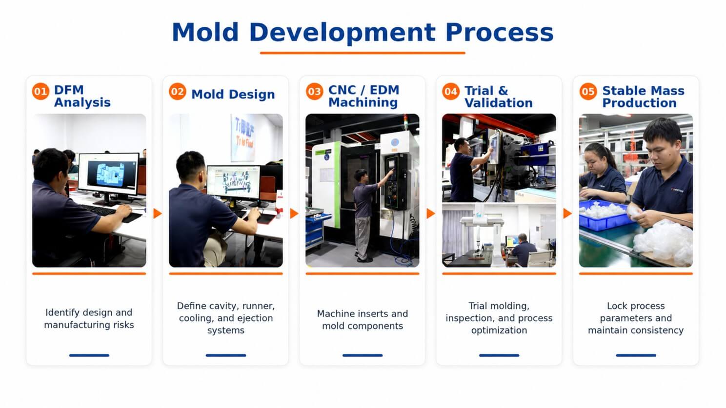
Step 1. DFM and mold-flow review
Before mold design starts, the part is reviewed for manufacturing risks. Typical items include draft angles, wall thickness, ribs and bosses, parting line, gate location, undercuts, slides and lifters, ejection, material shrinkage, and critical dimensions. Mold-flow analysis can also be used where filling behavior needs closer evaluation.
Mastars' mold engineering process includes a pre-tooling review, DFM report, and mold-flow analysis before moving into mold design. DFM is not just a checklist before production. It is where many tooling decisions are still cheap to change.
Step 2. Mold design
Once the part and process are reviewed, the tooling structure is developed. The mold design process includes the 3D mold design, component drawings, standard-parts list, material requirements, runner and cooling systems, and ejection structure. Mastars' tooling materials list both 3D and 2D mold design capability and the use of AutoCAD, UG, and Autodesk Moldflow.
Step 3. Mold manufacturing
The mold is then built through a series of machining and finishing operations. A typical workflow includes: steel and mold-base preparation → rough machining → heat treatment → grinding → CNC finishing → electrode preparation → EDM → wire cutting → fitting → polishing → mold assembly → trial molding.
Mold accuracy does not come from one machine. It comes from how the individual components are machined, inspected, fitted, and assembled into one working tool.
Step 4. Trial and optimization
The first mold trial is where the engineering team gets feedback from the actual molded part. The review should cover dimensions, appearance, filling, ejection, assembly, and functional features.
If a defect appears, the first step should be finding the cause. A short shot might involve filling conditions, venting, gate design, material behavior, or process settings. Warpage may involve cooling, shrinkage, part geometry, or processing conditions. The mold should not be modified simply because the defect appeared after tooling. The cause needs to be understood first.
Step 5. Production readiness
A good first sample is useful. It is not the same as stable production. For production, the mold and process need to repeatedly produce parts that meet the defined dimensional, appearance, functional, and assembly requirements. That difference between one good sample and repeatable production is one of the most important ideas in molding tooling.
What Drives Molding Tooling Cost?
There is no useful universal price for a mold. The part and the production requirement determine most of the cost.
| Cost Driver | Why It Matters |
|---|---|
| Part size | Affects mold size, material, and machining |
| Part geometry | Complex features increase tooling work |
| Cavity count | Adds components and balancing requirements |
| Tool material | Affects machining, durability, and tool life |
| Slides and lifters | Add mechanisms for undercuts |
| Surface finish | May require additional machining and finishing |
| Tolerance requirements | Increase machining and inspection requirements |
| Hot runner system | Adds system and design complexity |
| Expected tool life | Influences tooling material and structure |
A tooling quotation should therefore be evaluated against what it actually includes. Two molds can produce the same part but have different steel grades, cavity counts, cooling designs, mechanisms, surface finishes, and expected tool life. The cheaper quotation is not automatically the cheaper option over the life of the project.
That is why a detailed drawing and clear material and finish requirements make a tooling quotation more accurate. If the part changes after quotation, the tooling cost can change too. This is not unusual. It is a direct result of changing the manufacturing requirements.
Precision Matters, but the Part Still Comes First
Mold precision is only useful when it supports the required part performance. Mastars' tooling materials list a mold precision capability of 0.002 mm and injection precision of 0.05 mm. Those figures should not be interpreted as a promise that every feature on every molded part will hold 0.002 mm.
Actual molded-part accuracy depends on material shrinkage, part geometry, mold accuracy, cooling conditions, process stability, critical feature location, and inspection requirements. Standard molded-part tolerances depend on part size and material, while tighter tolerances for critical features require engineering review and optimized tooling and process control.
That is the more useful way to discuss precision. If a bearing seat or assembly interface is critical, identify it early. If a non-functional cosmetic dimension does not need the same tolerance, there is little reason to spend heavily to hold it to the same level. Good tooling is not about making every dimension as tight as possible. It is about putting precision where the product needs it.
When Is More Advanced Tooling Worth It?
Not every project needs the most advanced tooling solution.
Conformal cooling
Conformal cooling can be useful for difficult geometries where conventional cooling channels cannot provide an effective thermal path. The potential benefits include more uniform cooling, improved dimensional stability, and shorter cycle times.
But it should solve a real problem. If conventional cooling already gives sufficient control, a more complicated tooling solution may not provide enough return.
Multi-cavity and family molds
These can improve output and reduce unit cost when production volume justifies them. They also require attention to cavity balance, filling consistency, cooling, and process monitoring. Cavity layout, filling consistency, mold balance, cycle time, and tooling cost optimization remain key engineering considerations.
Metal 3D printing and complex inserts
Additive manufacturing can be considered where a conventional insert or cooling approach creates a genuine design limitation. The question should be: what manufacturing problem does the added complexity solve? Not: can we use a newer technology?
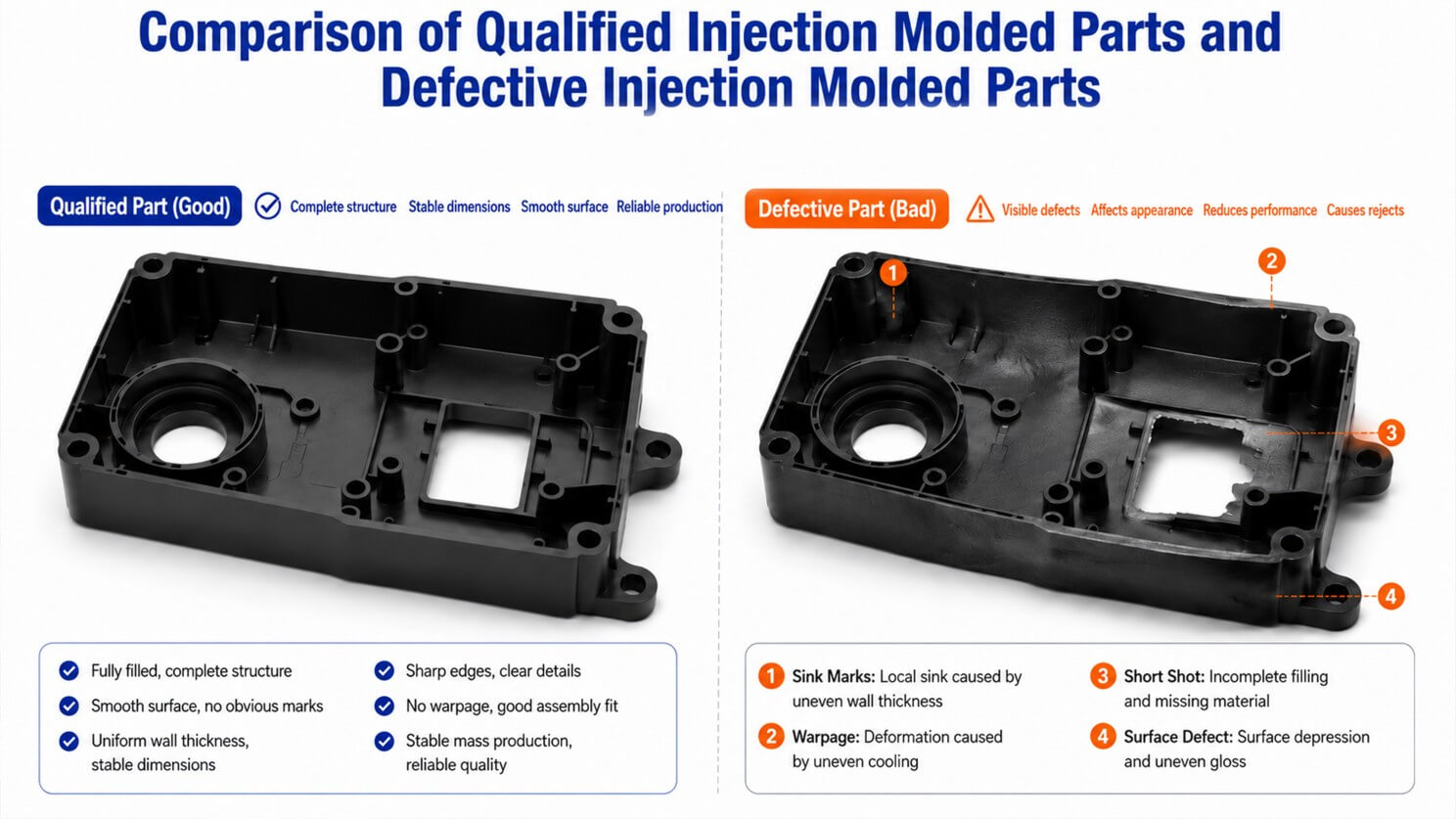
When a Molded Part Has a Defect, Start With the Cause
A defect appears on the part, and the mold gets blamed. Sometimes that is correct. Sometimes it is not.
| Part Symptom | Possible Tooling-Related Cause |
|---|---|
| Short shot | Gate, runner, filling, or venting |
| Warpage | Cooling imbalance or geometry |
| Sink marks | Local thickness, cooling, or packing |
| Flash | Parting-line condition or alignment |
| Ejection marks | Ejector layout or release |
| Weld lines | Flow path or gate location |
These are possible causes, not automatic diagnoses. For example, warpage may involve the mold, material shrinkage, part geometry, or process conditions. A sensible troubleshooting sequence is: identify the symptom → check the likely variables → find the root cause → change only what needs changing. This avoids a common and expensive mistake: modifying the mold based on an assumption and then discovering that the original problem came from somewhere else.
What Should Be Checked Before a Mold Is Released?
Before production starts, the following questions should have clear answers:
- Has the part undergone DFM review?
- Are critical dimensions identified?
- Is the parting line appropriate?
- Has the gate location been reviewed?
- Are draft and ejection adequate?
- Have cooling requirements been considered?
- Has the tooling been trialed?
- Have dimensions and appearance been checked?
- Do functional and assembly features work?
- Is the process stable enough for the intended production volume?
- Are inspection and quality requirements documented?
Mastars' manufacturing organization is built around connecting engineering design, tooling, injection molding, quality, and production rather than treating each stage as a separate supplier task. That integration is important when the part is complex. Instead of asking the customer to coordinate mold design with one supplier, molding with another, machining with another, and assembly somewhere else, the goal is to keep the manufacturing decisions connected.
Conclusion: Good Molding Tooling Makes Production More Predictable
Good molding tooling starts before the mold is built. Review the part early. Check the features that affect filling, cooling, ejection, and assembly. Choose the tooling material and cavity strategy according to the real production requirement. Validate important tooling decisions before they become expensive to change.
And when the mold is ready, do not judge it only by the first acceptable sample. The real test is repeatability. A mold that produces one acceptable part proves that the geometry can be produced. A mold and process that repeatedly produce parts within the defined requirements are what make production reliable.
For Mastars, the goal is not simply to build a mold. It is to make the path from part design → DFM → tooling → molding → inspection → production easier for the customer to manage. That is the practical meaning of Make life simple.
Have a Part in Development?
If you already have a CAD model or drawing, Mastars can review the part structure, material, critical features, and tooling requirements before mold development begins. Upload your CAD files and let our engineers look at the tooling risks before they become expensive mold changes.

Frequently Asked Questions
What is molding tooling?
Molding tooling refers to the mold and related tooling systems used to produce molded parts repeatedly. For injection molding, this normally includes the core, cavity, runner and gate system, cooling system, ejection system, and any slides, lifters, or inserts required by the part design.
What is the difference between molding tooling and an injection mold?
In many manufacturing discussions, the terms are used interchangeably. More broadly, molding tooling can refer to the complete tooling strategy, while an injection mold is the physical mold used to form the plastic part.
How much does molding tooling cost?
There is no useful standard price. Tool size, part geometry, cavity count, tooling material, slides and lifters, surface finish, tolerance requirements, hot runner systems, and expected tool life can all affect the cost. A detailed CAD model and clear material and finish requirements make a tooling quotation more accurate.
Is aluminum tooling good enough for production?
It can be, depending on the part and production requirement. Aluminum tooling can be suitable for prototypes, bridge production, and selected lower-volume programs. For longer production runs, steel may provide better long-term tool life. The decision should be based on expected volume, material, geometry, surface requirements, and tool-life requirements.
When should I use prototype tooling instead of production tooling?
Prototype tooling makes more sense when the design still needs physical validation or when production volume is not yet clear. Production tooling becomes more appropriate once the design, material, quality requirements, and expected production demand are sufficiently stable.
What should a DFM review check before mold manufacturing?
A DFM review should look at draft, wall thickness, ribs, bosses, parting line, gate location, undercuts, slides, lifters, ejection, material shrinkage, and critical dimensions. For more complex parts, mold-flow analysis may also help identify filling and cooling risks.
Can tooling be validated before making the final metal mold?
Yes, depending on the project. Mastars has used PU tooling board to create surrogate mold inserts for prototype and small-batch validation. This approach can help check parting and draft, slider and ejector layouts, gate and runner geometry, and assembly fit before final metal tooling is committed.
What causes injection molding defects related to tooling?
Tooling can contribute to short shots, warpage, sink marks, flash, ejection marks, and weld lines through factors such as gate design, cooling, venting, parting-line condition, ejection layout, and mold accuracy. However, the mold is not always the root cause. Material, part design, and molding conditions should also be checked.
How important is mold precision for molded parts?
Mold accuracy is important, but it is only one part of final part accuracy. Material shrinkage, part geometry, cooling, process stability, and feature location also affect the molded result. Critical features should therefore be identified during engineering review instead of applying the same tight tolerance to every dimension.
How long does it take to make molding tooling?
Tooling lead time depends on mold size and complexity, cavity count, tooling material, machining requirements, surface finish, cooling design, slides and lifters, and validation requirements. A simple prototype tool and a complex production mold can have very different development timelines.
Hot Articles
Hot Tags
Stay Connected!


Manufacturing on Demand
Please fill in the following information to obtain plan details (information is confidential and not disclosed publicly), we will contact you within 24 hours, please keep your phone available!
Upload a 3D/2D model to see instant pricing, lead time, and DFM feedback.