



T0 to T3 Injection Mold Trials: Samples, Tool Corrections & Approval


An injection mold trial is a controlled molding run used to check how the tool, material, machine, and process work together before production. The trial generates evidence through molded samples, process records, dimensional results, defect observations, and corrective actions.
Completing the mold is only one milestone. A tool may open, fill, cool, and eject parts correctly while the parts still have problems with critical dimensions, assembly fit, warpage, cavity balance, or appearance. Mold trials provide the next layer of validation.
Important: T0, T1, T2, and T3 are commonly used labels, but their exact definitions are not standardized across all mold makers, customers, or quality systems. Trial scope, sample acceptance criteria, and production-approval requirements should be agreed in the tooling specification and project quality plan, with the approved drawing, inspection plan, and customer requirements used as the working reference.
A practical way to look at the stages is:
T0 / Initial Tool Check → T1 / First Engineering Samples → T2 / Correction Verification → T3 / Production-Readiness Validation
The number assigned to a trial matters less than the engineering question it is intended to answer and the evidence required for the next decision.
What Is an Injection Mold Trial?
An injection mold trial uses the actual or intended molding tool to evaluate tool operation, part formation, process conditions, and molded-part quality. It is not simply a dimensional inspection because the result depends on the interaction between mold design, resin behavior, machine capability, process settings, cooling, ejection, and part geometry.
A trial can answer questions such as:
- Does the mold open and close correctly?
- Are slides, lifters, cores, and ejectors working as intended?
- Does the cavity fill without unacceptable short shots, burn marks, or severe weld lines?
- Are critical-to-quality (CTQ) dimensions within the agreed requirements?
- Does the part assemble correctly with mating components?
- Is warpage affecting fit or appearance?
- Can a defect be addressed through process adjustment, or does the tool need modification?
- Can the agreed conditions repeatedly produce acceptable parts?
The cause of a molding defect is not always the mold itself. Material condition, part geometry, machine capability, process settings, cooling, venting, and tooling can all contribute to the result.
For example, a visible sink mark may require a review of local wall thickness, gate location, packing conditions, and cooling rather than a single parameter change. The trial gives the team physical evidence to narrow down the cause.
How Are T0, T1, T2, and T3 Mold Trial Stages Used?
T0–T3 can be treated as a sequence of engineering checkpoints: first establish basic tool function, then review meaningful parts, verify corrections, and finally evaluate repeatability under production-intent conditions. They are not four mandatory runs for every mold project.
| Trial Stage | Primary Objective | Typical Checks | Typical Evidence | What Should Not Be Assumed | Next Decision |
|---|---|---|---|---|---|
| T0 / Initial Tool Check | Confirm basic tool operation and initial molding feasibility | Tool actions, filling, venting, cooling, ejection, obvious defects | Trial notes, photos, initial samples, issue list | Final dimensions, cosmetics, yield, or production capability | Tune process or correct tool issues |
| T1 / Engineering Samples | Establish an engineering baseline for the part | CTQs, GD&T, appearance, fit, assembly, function, shrinkage, warpage | Labeled samples, dimensional report, trial report, action list | The tool is final or production-ready | Review issues and plan corrections |
| T2 / Correction Verification | Confirm that defined problems were addressed | CTQs, defects, assembly, cavity consistency, revised process | Revised samples, inspection results, change record | One improved run proves long-term stability | Move toward production validation or correct again |
| T3 / Production-Readiness Validation | Evaluate repeatable output under agreed conditions | Stability, cycle time, dimensions, appearance, cavity consistency, inspection | Production-intent samples, parameter record, approval documents | T3 automatically releases the mold for production | Release, pilot production, or further action |
A simple single-cavity mold and a complex multi-cavity housing may follow very different trial paths. Part geometry, resin, mold maturity, cosmetic requirements, dimensional tolerances, and changes made after each run all affect how many trials are needed.
T0: Can the Mold Run and Produce a Usable First Fill?
A T0 trial is generally used as the initial tool check. The first run focuses on safe mold operation and basic molding feasibility so the team can produce meaningful samples for engineering review.
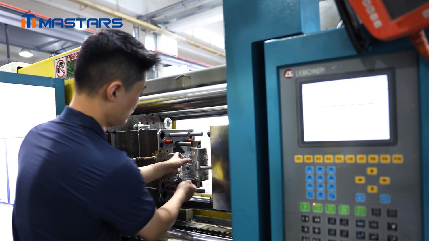
What engineers check first
The first run is not the time to chase every cosmetic detail. The priority is finding problems that could prevent useful samples from being produced.
Mold operation
- Mold opening and closing
- Guide and alignment components
- Slides, lifters, cores, and other moving mechanisms
- Ejection stroke and part release
- Interlocks and mechanical interference
- Cooling connections and leakage
- Hot-runner operation where applicable
Initial molding behavior
- Filling pattern
- Short shots
- Flash
- Burn marks
- Severe weld lines
- Sticking during ejection
- Gate behavior
- Venting
- Obvious deformation
The first samples also show where the next engineering review should focus. A short shot in a thin section may involve filling conditions, venting, gate design, material behavior, or machine capability. A part that sticks during ejection may point toward draft, surface condition, ejection layout, or process conditions.
What should come out of T0?
A T0 record should connect the samples to the conditions under which they were produced. The package may include:
- Initial molded samples
- Trial notes
- Machine and material information
- Key process settings
- Photos of visible defects
- Open issue list
- Recommended corrective actions
A successful first shot establishes a starting point. It does not establish final dimensional performance, cosmetic approval, long-term repeatability, or production capability.
T1: What Should the First Engineering Samples Reveal?
A T1 sample usually provides the first meaningful engineering baseline for the molded part. The review should compare the actual part with the drawing, CTQ requirements, assembly interfaces, appearance criteria, and functional expectations.
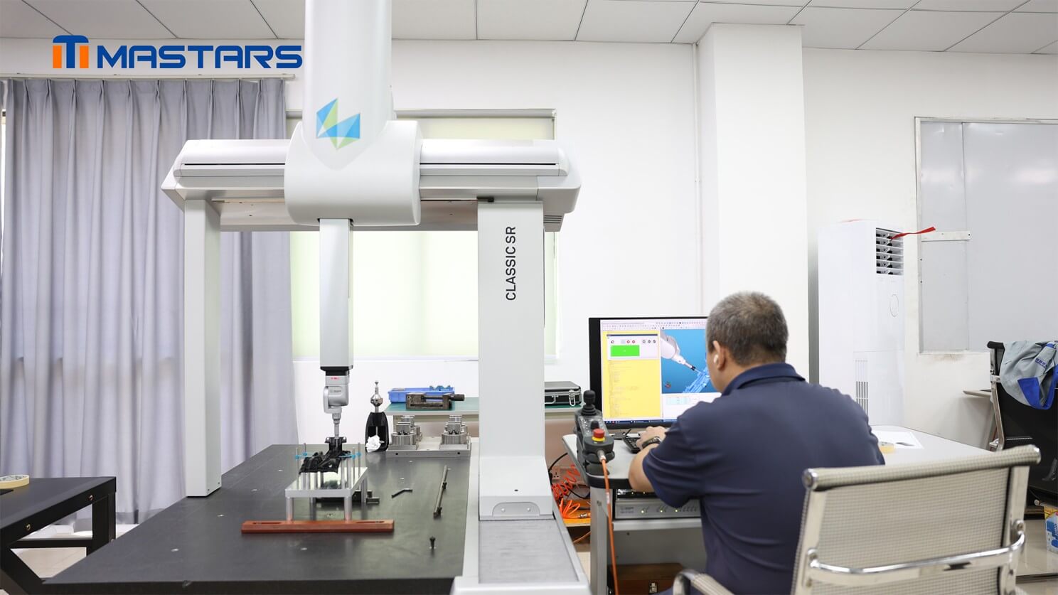
Start with the features that matter to the product
Not every dimension carries the same engineering risk. Identify the critical-to-quality (CTQ) features first.
These may include:
- Connector openings
- Mating surfaces
- Snap-fit dimensions
- Screw bosses
- Thread features
- Sealing interfaces
- Assembly datums
- Critical wall sections
- Functional features controlled by GD&T
An enclosure can have dozens of dimensions within their nominal ranges and still fail assembly because one connector opening is displaced. That is why dimensional inspection should be combined with actual fit and functional checks when the design requires them.
Appearance needs context
A cosmetic review may cover:
- Sink marks
- Weld lines
- Flow marks
- Splay
- Burn marks
- Flash
- Gate vestige
- Ejector marks
- Color variation
- Surface texture
- Gloss differences
- Stress whitening
The location of a defect matters. A gate vestige on an internal surface may be acceptable, while the same feature on a customer-facing surface may require a different gate or cosmetic strategy.
The same principle applies to ejector marks, weld lines, and texture transitions. Acceptance should follow the approved cosmetic standard rather than a generic rule that every visible molding mark is unacceptable.
Check cavity-to-cavity behavior
For a multi-cavity mold, one good part is not enough to describe the tool.
If one cavity produces a dimension close to nominal while another is consistently shifted, the issue may involve cavity balance, filling, cooling, or tooling dimensions. The first engineering samples are a good point to establish whether the cavities are behaving consistently.
What should the T1 package contain?
A T1 package may include:
- Clearly labeled samples
- Dimensional or CTQ inspection results
- Trial report
- Cosmetic observations and defect photos
- Open issue list
- Corrective action list
- Proposed next-trial conditions
The sample should be traceable to the material, machine, process conditions, cavity, and drawing revision used during the trial.
The same distinction between prototype validation and molding validation appears in a Mastars multi-port USB charger enclosure project. The prototype stage addressed connector positioning, PCB accommodation, enclosure fit, fastening, and assembly relationships. Before tooling, the design still required review of wall thickness, ribs, bosses, draft, parting strategy, gate location, ejection, shrinkage, warpage, and cosmetic surfaces.
T2: Did the Correction Actually Fix the Problem?
T2 is generally used to verify changes made after the earlier trial. The team compares the revised samples with the original issue, checks whether the corrective action worked, and looks for side effects introduced by the change.
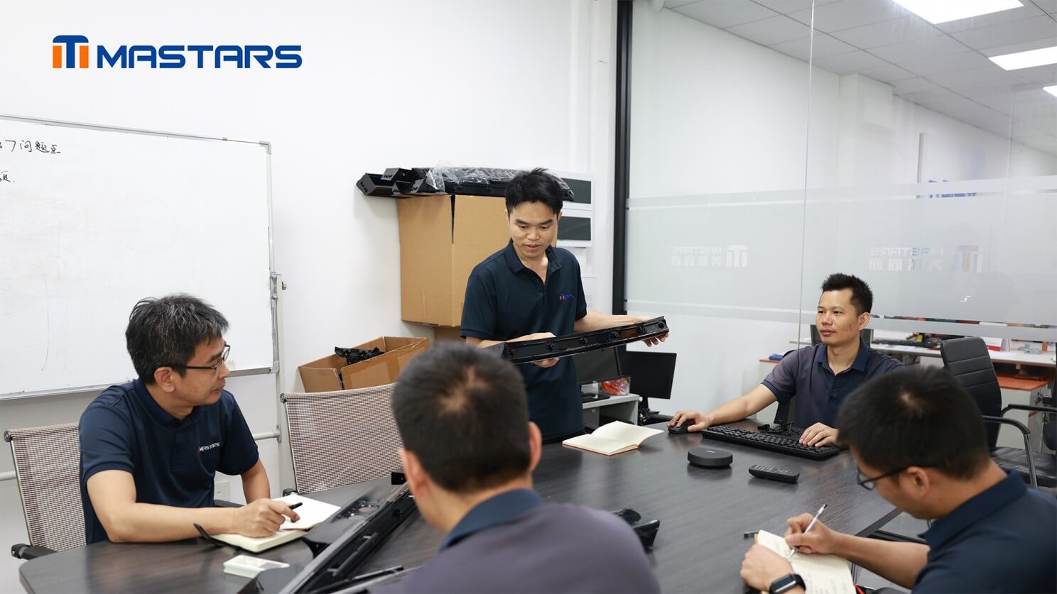
Not every defect requires cutting steel
A process adjustment may address problems related to:
- Injection speed
- Melt temperature
- Mold temperature
- Packing or holding pressure
- Holding time
- Cooling time
- Material drying
A tooling correction may involve:
- Gate or runner modification
- Venting
- Cooling layout
- Ejection
- Local cavity dimensions
- Parting surfaces
- Slides or lifters
- Other mold geometry
The decision should follow the suspected cause.
Consider a visible sink mark. Higher packing pressure may improve the surface, but the same change can affect flash, residual stress, or dimensions elsewhere. If the root problem is local wall thickness or cooling, repeated parameter changes may only shift the defect.
In injection molding, melt flow and polymer orientation, temperature differences during cooling and shrinkage, gate location, runner design, cooling, product geometry, and ejection can all influence residual stress, dimensional change, warpage, cracking, or whitening. Mastars’ tooling work addresses these factors together during mold development rather than treating each defect as an isolated process setting.
What should T2 demonstrate?
The revised sample should be compared directly with the original problem.
For example:
Original issue: connector opening out of tolerance
Change: tool correction to the affected feature
T2 check: repeat the same dimensional inspection
Result: determine whether the correction moved the feature as intended
The same approach applies to warpage, appearance defects, assembly interference, and cavity-to-cavity differences.
T2 should show whether the corrective action addressed the underlying cause, not just whether the sample looks better.
T3: Can the Process Repeat Under Production-Intent Conditions?
T3 is commonly used for production-readiness validation. At this stage, the team evaluates whether acceptable parts can be produced repeatedly under conditions representative of production.
T3 requirements should be tied to the project’s acceptance criteria and production requirements.
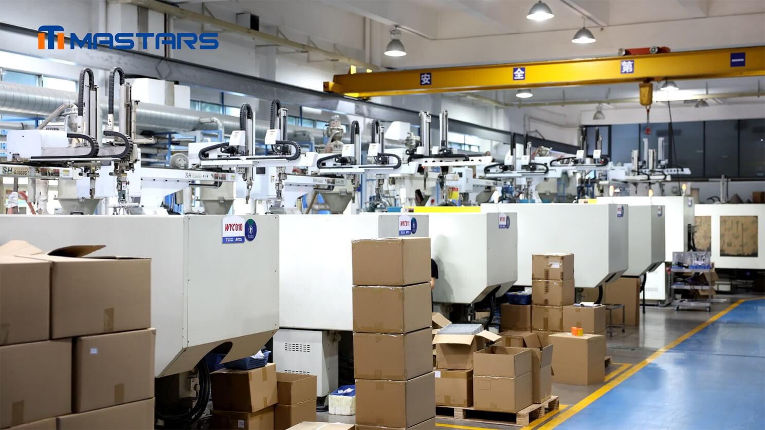
Production-intent conditions matter
Where required, validation should use the intended production material, an appropriate production machine, agreed process settings, and the target cooling and cycle conditions.
The review may cover:
- Dimensional repeatability
- CTQ features and GD&T
- Appearance consistency
- Cavity-to-cavity consistency
- Cycle time
- Process stability
- Scrap or yield trends
- Assembly fit
- Functional performance
- Material traceability
- Inspection results
The team may also evaluate what happens over repeated cycles. Thermal behavior, mold movement, ejection, and process drift can become more visible during a sustained run than during a small number of sample shots.
One good sample does not establish repeatability
This matters most for parts with tight interfaces, multiple cavities, or demanding cosmetic surfaces.
Gate location, runner design, cooling paths, wall-thickness variation, ejection strategy, and material shrinkage can affect residual stress, warpage, dimensional stability, and surface appearance. These relationships are why production-intent validation needs to be connected to the tooling decisions made earlier in the project.
What does T3 mean for production release?
T3 does not automatically release a mold for mass production.
Depending on the project, final release may require:
- Customer sample approval
- Approved part and mold revisions
- Dimensional inspection
- First Article Inspection (FAI), where required
- Material certificates or traceability records
- Production Part Approval Process (PPAP), where applicable
- Process capability studies, where required
- Functional or regulatory testing
- Project-specific quality documentation
The release criteria should be agreed before the validation run.
Mold Trial Checklist: What Should Be Reviewed at Every Stage?
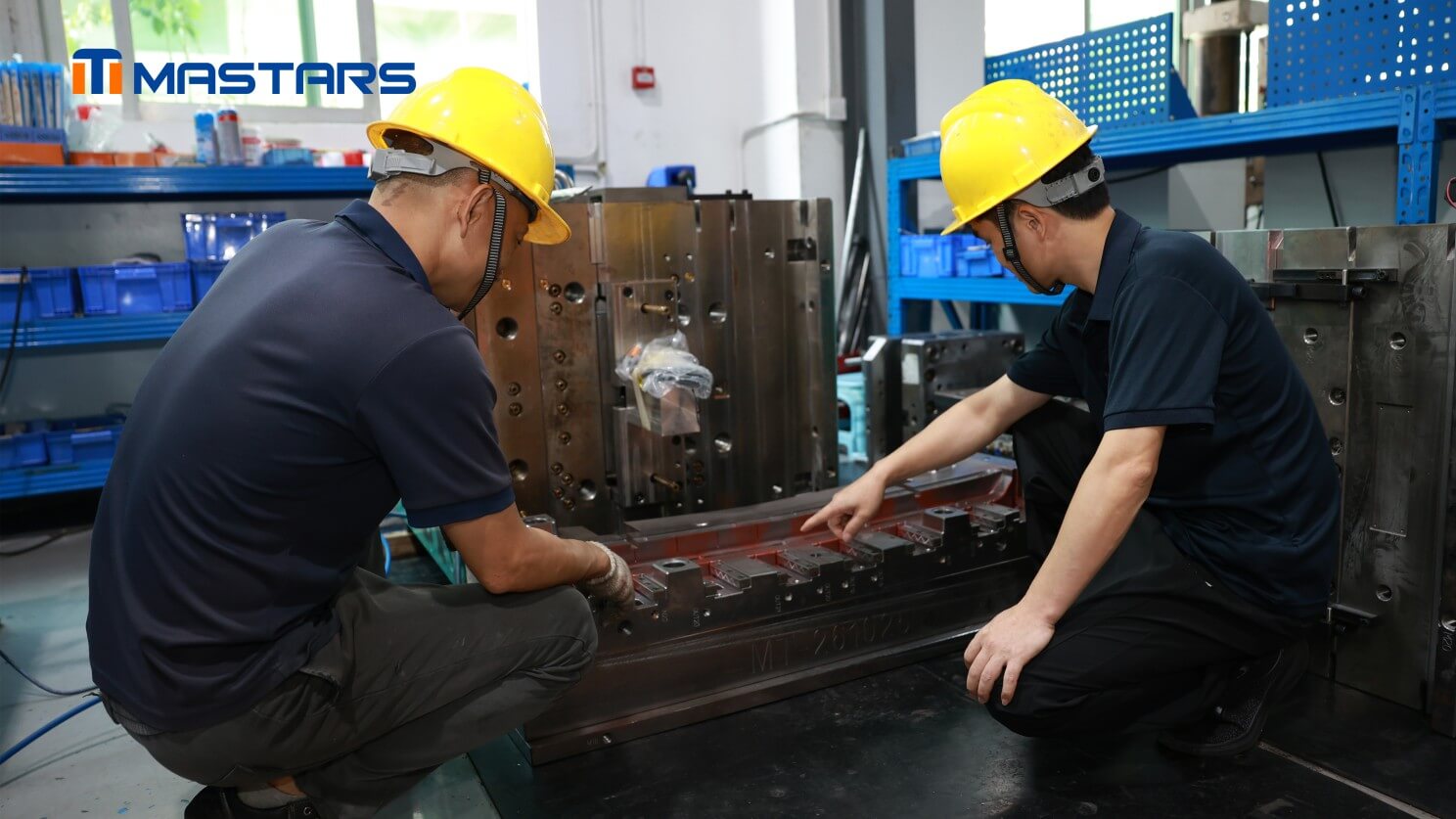
A mold trial checklist should cover tool function, part formation, geometry and assembly, material behavior, process conditions, and documentation. The depth changes from T0 to T3, but these categories remain connected throughout the project.
Tool function
- Mold opening and closing
- Guide components and alignment
- Slides, lifters, cores, and ejection
- Interlocks and mechanical interference
- Cooling circuits and water leakage
- Temperature control
- Hot-runner performance where applicable
Part formation
- Filling and packing
- Venting
- Gate behavior
- Runner balance
- Demolding
- Short shots
- Flash
- Burn marks
- Sink marks
- Weld lines
- Splay
- Gate vestige
Part geometry and assembly
- CTQ dimensions
- Geometric Dimensioning and Tolerancing (GD&T)
- Warpage
- Shrinkage
- Mating-part fit
- Clips and snap fits
- Threads
- Inserts
- Seals
- Functional features
Appearance and material behavior
- Surface texture
- Gloss
- Color
- Flow marks
- Ejector marks
- Stress whitening
- Resin condition
- Actual resin grade
- Color and additives or fillers
- Drying requirements where relevant
Process and documentation
- Machine ID
- Material lot
- Drying conditions
- Mold temperature
- Key process settings
- Cycle time
- Sample identification
- Dimensional results
- Cosmetic observations
- Open issues
- Corrective actions
- Next-trial requirements
A defect should not automatically be classified as a tooling problem. Material condition, part design, machine capability, and molding conditions can all influence the result. Good trial analysis brings the design, tooling, molding, and quality teams back to the same evidence.
How Should You Prepare for a Mold Trial?
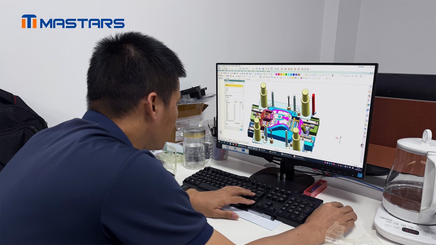
The most effective preparation happens before the machine runs. Provide the latest drawing and CAD revision, CTQs, material requirements, assembly criteria, cosmetic standards, sample requirements, and approval process so the trial has a defined target.
Design information
Prepare:
- Approved 2D drawing
- Latest 3D CAD revision
- CTQ dimensions
- GD&T requirements
- Critical interfaces
- Assembly requirements
- Functional requirements
- Cosmetic surfaces
- Parting-line or gate restrictions where relevant
Material information
Confirm:
- Resin grade
- Color
- Filler or additive
- Flame-retardant, medical, food-contact, or other special requirements
- Material supplier where relevant
- Drying and preconditioning requirements
- Production-intent material requirements
A prototype resin or substitute material should not automatically be treated as equivalent to the final production resin.
Sample and inspection requirements
Define:
- Sample quantity
- Cavity identification
- Sample labeling
- Dimensional inspection scope
- Cosmetic acceptance criteria
- Assembly samples
- Functional tests
- Customer feedback timing
- Sample sign-off process
If the product has mating parts, inserts, fasteners, seals, or other hardware, provide those components when they are needed to evaluate the assembly.
Project controls
Agree on:
- Trial stage
- Mold revision
- Machine
- Material
- Acceptance criteria
- Trial-report format
- Issue-action log
- Change approval
- Next-trial decision
This prevents a common project gap: the supplier considers the trial complete because parts were molded, while the customer is still waiting for dimensional data, assembly samples, or a defined approval package.
Why Prototype Approval Does Not Automatically Validate Injection Molding
Prototype approval confirms that the product concept works against the tests performed on the prototype. It does not by itself validate the behavior of the same geometry in a production injection-molding process, where shrinkage, warpage, draft, gates, parting lines, cooling, and ejection become part of the manufacturing problem.
In the Mastars multi-port USB charger enclosure project, the prototype route was used to evaluate geometry, connector positioning, PCB fit, enclosure assembly, and fastening. Before tooling, the design still needed injection-molding review of wall sections, ribs, bosses, draft, gates, ejection, shrinkage, warpage, and cosmetic surfaces.
The manufacturing route should therefore follow the validation objective.
SLA can answer questions about geometry, dimensions, appearance, and basic fit.
CNC-machined engineering plastics can support connector positioning, PCB installation, fastening, and repeated assembly checks.
Vacuum casting or other low-volume routes can provide engineering samples, pilot quantities, or market-validation parts.
Injection molding becomes more relevant when the team needs to validate production-intent material, molded geometry, tooling behavior, and repeatable output.
If the design is still changing frequently, prototype or bridge tooling may reduce the cost of further iterations. The decision should consider expected volume, tool life, material, dimensional and cosmetic requirements, and the likelihood of engineering changes.
How Should a Mold Trial Report Be Reviewed?
A mold trial report should allow an engineer or buyer to understand what was run, what changed, what the samples showed, and what happens next. The report is most useful when trial conditions can be traced directly to the samples and inspection results.
Look for:
- Trial conditions — stage, date, mold ID, machine, material, material lot, and relevant process settings.
- Sample identification — cavity, sample number, revision, and any special condition used during the trial.
- Results — dimensional data, CTQ results, appearance observations, assembly findings, and functional results where applicable.
- Open issues — defect, location, severity, suspected cause, and whether the issue points toward process, material, design, or tooling.
- Next action — process adjustment, mold correction, additional inspection, customer review, or next trial.
Traceability is critical. If a gate was modified between T1 and T2, the report should make it possible to compare the affected filling, appearance, dimensions, or assembly behavior before and after the change.
That is far more useful than a report that simply states “sample approved.”
Conclusion: What Should a Mold Trial Actually Tell You?
An injection mold trial should give the project team enough evidence to make the next manufacturing decision with controlled risk. T0 checks whether the tool can run and produce usable parts; T1 establishes the engineering baseline; T2 verifies corrections; and T3 evaluates repeatability under production-intent conditions.
The number of trials should follow the evidence rather than a predetermined T0–T3 sequence. A complex multi-cavity part with tight CTQs, demanding cosmetic surfaces, or difficult materials may require more iteration, while a simpler project may move through the stages with fewer runs.
Before each trial, make sure the drawing revision, material, CTQs, inspection requirements, sample expectations, and acceptance criteria are clear. After each trial, the report should connect conditions, findings, corrective actions, and the next decision.
The next manufacturing decision should follow the trial evidence, not simply the number assigned to the run.
Need Support From Tooling Trials to Production?
Mastars can support the engineering path from DFM and mold development through trial molding, sample inspection, tooling corrections, and production transition. Share your CAD files, critical dimensions, material requirements, and expected volume to discuss the appropriate tooling and validation plan.
FAQ About T0, T1, T2, and T3 Mold Trials
What does T0 mean in injection molding?
T0 commonly refers to an initial mold-function check or first trial run, but the definition varies by supplier and project. Some teams use T0 for the first shot; others use it for an initial tool check before their T1 samples. Before the trial, confirm what T0 means in the tooling specification and what samples, inspection results, and decisions are expected from that run.
Is T1 the first sample from an injection mold?
In many projects, T1 refers to the first meaningful engineering samples, but it is not a universal definition. Some suppliers call the first molded parts T0 or “first shot.” Agree on the terminology, sample requirements, inspection scope, and acceptance criteria before the trial.
What is checked during a T1 mold trial?
A T1 review typically covers critical dimensions, GD&T, appearance, filling, shrinkage, warpage, assembly fit, functional features, and mold actions. Material condition and process settings should also be recorded. For multi-cavity tools, cavity-to-cavity variation is worth checking early because one acceptable cavity does not describe the entire mold.
What is the difference between T1 and T2 samples?
T1 generally establishes the first engineering baseline; T2 checks whether changes made after T1 solved the identified problems. The comparison should connect the original defect to the corrective action and the new inspection result. T2 should also be checked for side effects, such as a process change that improves one defect while shifting another dimension or cosmetic issue.
Does T3 mean the mold is ready for mass production?
No. T3 is commonly used for production-readiness validation, but the label itself does not constitute production approval. Release may still require customer sample approval, dimensional inspection, FAI, material documentation, process studies, functional testing, or other project-specific requirements. The approved drawing, inspection plan, and quality plan should define the release criteria.
How many mold trials are normally required?
There is no fixed number. The number of trials depends on part complexity, material, mold maturity, dimensional and cosmetic requirements, cavity count, customer changes, and what the previous run reveals. Good DFM can reduce avoidable tooling problems before the first trial, but the molded part still needs to be validated under the conditions required by the project.
Hot Articles
Hot Tags
Stay Connected!


Manufacturing on Demand
Please fill in the following information to obtain plan details (information is confidential and not disclosed publicly), we will contact you within 24 hours, please keep your phone available!
Upload a 3D/2D model to see instant pricing, lead time, and DFM feedback.