



Vacuum Forming vs Pressure Forming: Differences, Costs, Materials, and Design Considerations


A thermoformed part can look correct on the first sample and still create problems later. Wall thickness may fall off in a deep draw, a textured surface may not reproduce clearly, or a mounting hole may move enough to affect assembly. The forming process you choose affects how much of that risk carries into production.
Vacuum forming uses atmospheric pressure to draw a heated thermoplastic sheet against a mold. Pressure forming adds compressed air on the opposite side, increasing the forming force and improving contact with the mold.
For large, relatively simple parts and cost-sensitive low-volume work, vacuum forming is often sufficient. Pressure forming becomes useful when the part requires finer surface detail, molded texture, embossed features, or more defined contours. Both processes still require attention to material behavior, wall distribution, cooling, trimming, and final tolerances.
The sections below focus on the engineering factors that usually determine that choice: forming force, detail, material behavior, tooling, geometry, and production requirements.
Vacuum Forming vs Pressure Forming: What Is the Difference?
Both processes heat a thermoplastic sheet and form it over a mold. The difference is the source of forming pressure: vacuum forming uses the pressure difference created by evacuating air beneath the sheet, while pressure forming adds compressed air above it. That additional pressure improves contact between the sheet and mold surface.
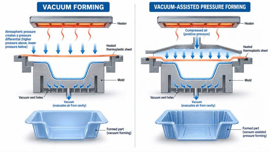
Vacuum forming vs pressure forming cross-section showing vacuum pressure and positive air pressure on a heated thermoplastic sheet.
Vacuum forming
In vacuum forming, the heated sheet is positioned over the mold and air is removed from beneath it. Atmospheric pressure then pushes the softened sheet against the mold.
A typical cycle is:
- Heat the thermoplastic sheet.
- Position it over the mold.
- Apply vacuum.
- Form the sheet against the mold.
- Cool and release the part.
- Trim the formed shell.
- Machine holes or functional interfaces if required.
At sea level, a full vacuum provides a theoretical pressure differential of about 14.7 psi. Over a large forming area, that still creates substantial tool loads. RIDAT notes that vacuum-forming forces are often underestimated for this reason.
Pressure forming
Pressure forming follows the same basic heating and forming sequence, but compressed air is introduced above the heated sheet while vacuum is applied below it.
The higher pressure improves contact with the mold and allows finer surface features to be reproduced more clearly. RIDAT specifically identifies improved detail and in-mold texturing as key pressure-forming advantages, while also noting that the tooling is more complicated and expensive.
The higher pressure also places greater demands on the tooling and pressure-control system.
Quick Comparison: Vacuum Forming vs Pressure Forming
For most engineering decisions, the useful distinction is not simply which process applies more pressure. It is whether the added forming capability solves a requirement on the finished part.
| Factor | Vacuum Forming | Pressure Forming |
|---|---|---|
| Forming force | Atmospheric pressure through vacuum | Vacuum plus positive air pressure |
| Tooling / equipment | Simpler for suitable applications | More complex |
| Surface detail | Limited to moderate | Better suited to fine detail |
| Texture / lettering | Moderate reproduction | Better reproduction |
| Large parts | Strong fit | Equipment-dependent |
| Dimensional control | Material- and process-dependent | Feature definition can improve, but remains process-dependent |
| Cost direction | Lower tooling investment | Higher tooling investment |
| Typical use | Large covers, trays, guards, simple housings | Detailed or appearance-critical panels and housings |
The process should be selected from the requirements of the finished part rather than from forming pressure alone.
Forming Detail and Surface Finish
Pressure forming gives the sheet closer contact with the mold, which helps reproduce textures, lettering, ribs, louvers, recessed features, and other visible details. This is particularly useful when the exterior surface is part of the product's appearance rather than simply a protective shell.
Sharp corners, ribs, and lettering
Deep or narrow features force the heated sheet to stretch into localized areas. Vacuum forming can reproduce many such features, but definition becomes more difficult as the geometry becomes deeper, narrower, or sharper.
Pressure forming is worth evaluating when the design includes:
- Molded-in texture
- Embossed logos
- Fine lettering
- Defined ribs
- Louvers or vents
- Recessed cosmetic details
- More controlled exterior contours
The mold still needs appropriate geometry. A sharp corner can create localized thinning or webbing even when the forming force is sufficient. RIDAT's design guidance recommends generous radii and notes that sharp corners increase the risk of webbing.
Surface definition is not dimensional accuracy
A part can reproduce a textured surface very well and still require post-form machining for a critical mounting hole.
Thermoformed dimensions are affected by sheet behavior, heating uniformity, mold geometry, cooling, shrinkage, warpage, and trimming. For that reason, visible surface quality and functional dimensional control should be reviewed separately.
Material, Sheet Thickness, and Wall Distribution
Thermoforming stretches sheet rather than filling a closed cavity. As the material moves into a deep mold, the available sheet has to cover a larger surface area, so the finished wall thickness varies across the part.
Open University Manupedia reference lists common thermoforming sheet thicknesses from 0.60 to 13 mm and typical draw ratios from about 2:1 to 5:1. It also notes that areas reaching the mold later are usually the thinnest. These are useful industry reference ranges, not universal limits for every material or machine.
Common thermoforming materials
| Material | Why it may be selected | Engineering consideration |
|---|---|---|
| ABS | Toughness, appearance, general-purpose housings | Grade and heat behavior |
| HIPS | Cost-sensitive parts and packaging | Lower mechanical performance |
| PETG | Formability and clarity | Temperature and chemical requirements |
| Polycarbonate | Impact resistance | Processing window and cost |
| PMMA | Optical clarity and appearance | Impact sensitivity |
| PP | Chemical resistance and low density | Forming and shrinkage behavior |
| PVC | Chemical resistance and cost | Grade-specific requirements |
The exact sheet grade matters as much as the polymer family. Mechanical, thermal, chemical, cosmetic, and regulatory requirements should be checked before material selection is finalized.
Starting thickness is not finished thickness
A 3 mm sheet does not produce a 3 mm wall throughout a formed part.
Deep cavities, corners, and other areas requiring substantial stretching can become considerably thinner than the original sheet. OpenLearn describes this relationship directly: wall thickness decreases as the formed surface area increases relative to the original sheet area.
For a production part, specify the minimum functional wall thickness at the critical location, rather than relying only on nominal sheet gauge.
Draw depth and plug assist
Deep draws deserve attention during DFM. As the depth increases relative to the opening, more material has to move into the cavity and wall distribution becomes harder to control.
Plug assist can pre-stretch the heated sheet before vacuum or pressure completes the forming operation. It can improve material distribution in deep features, but it also affects tooling and process requirements.
For a deep enclosure, sheet gauge, draw ratio, corner radii, preforming method, and minimum wall thickness should therefore be reviewed together.
Tooling and Cost
Vacuum forming generally has a lower tooling barrier because the mold does not need to withstand the same positive air pressure used in pressure forming. Pressure forming adds equipment and tooling requirements, so the higher upfront investment needs to be justified by the part's geometry or appearance requirements.
Vacuum-forming tooling
Suitable vacuum-forming molds can be produced from wood, metal, plastic, plaster, and other tooling materials. OpenLearn notes that thermoforming tooling is relatively inexpensive compared with many other forming processes.
This makes simpler tooling attractive when:
- The part is large.
- Geometry is relatively simple.
- Design changes are expected.
- Production volume is limited.
- Fine molded detail is not critical.
For an early prototype, spending heavily on production-grade tooling before the geometry is proven can be difficult to justify.
Pressure-forming tooling
Pressure-forming tools need to accommodate the additional air pressure while maintaining the surface detail and venting needed for the part.
That investment becomes easier to justify when the design depends on molded texture, crisp lettering, defined ribs, louvers, or other features that directly affect the finished product.
Compare the finished part, not only the mold
A realistic cost calculation includes:
Material + tooling + forming + trimming + finishing + scrap + inspection + assembly
A low tooling price can lose its advantage if the resulting part requires extensive trimming, machining, cosmetic rework, or additional inspection. Conversely, the higher tooling cost of pressure forming may be reasonable when better feature reproduction reduces downstream work.
Choosing Between Vacuum Forming, Pressure Forming, and Injection Molding
The comparison changes when the design depends on integrated features, tighter functional dimensions, or higher production volumes. Vacuum forming is well suited to large and relatively simple shells; pressure forming extends thermoforming into more detail-focused applications; injection molding becomes more attractive as integrated geometry and production requirements increase.
| Part requirement | Process to evaluate |
|---|---|
| Large simple cover | Vacuum forming |
| Tray or protective shell | Vacuum forming |
| Low-volume enclosure | Vacuum forming |
| Fine molded texture | Pressure forming |
| Embossed logo or lettering | Pressure forming |
| Defined ribs or louvers | Pressure forming |
| Appearance-critical panel | Pressure forming |
| Integrated bosses or clips | Injection molding or hybrid route |
| Complex internal geometry | Injection molding |
| Tight functional interfaces | Injection molding, CNC, or hybrid route |
| High-volume complex housing | Injection molding |
These are process directions rather than fixed rules. A large, low-volume enclosure may stay with vacuum forming even when a pressure-forming process could reproduce more detail. Conversely, a smaller part with demanding cosmetic requirements may justify pressure forming at a lower quantity.
Geometry and Production Volume
Before tooling, review five areas together: detail, tolerance, surface requirements, geometry, and volume.
Detail: Fine texture, lettering, ribs, and louvers place greater demands on mold contact and surface reproduction.
Tolerance: Thermoformed dimensions are influenced by material shrinkage, cooling, warpage, mold accuracy, and trimming. Critical holes and mating interfaces may need CNC trimming or machining after forming.
Surface: A visible A-surface with controlled texture has different requirements from a concealed protective cover.
Geometry: Draw depth, undercuts, corner radii, ribs, recesses, and integrated features should be reviewed before the mold is released.
Volume: At low volume, tooling investment has a larger effect on unit cost. As volume increases, cycle time, scrap, consistency, automation, and tool life become more important.
There is no universal quantity at which a project should move from vacuum forming to pressure forming or injection molding. The geometry and complete manufacturing route determine the economics.
Thermoforming Design Considerations
Good thermoforming design starts before the mold is cut. Draft, corner radius, draw depth, venting, trimming allowance, shrinkage, and warpage all affect whether the finished part will meet its functional requirements.
Draft
Draft allows the formed part to release from the mold without excessive friction or deformation. RIDAT recommends allowing as much draft as the design permits and gives minimum references of 3° for male molds and 1° for female molds. Textured surfaces may require additional draft to prevent the texture from scraping during ejection.
Corner radius
Sharp corners force the sheet to stretch into a small region and can increase thinning and webbing.
OpenLearn gives 4–5 times sheet thickness as a general reference for bend and corner radii. The appropriate value still depends on the material, tool geometry, draw depth, and required wall thickness.
Venting
Trapped air prevents the sheet from fully contacting the mold. Venting is particularly important around recesses, corners, pockets, and fine surface features. RIDAT's toolmaking guidance specifically calls for attention to vent placement in these areas.
Trimming allowance
The formed shell normally needs trimming before it becomes an assembly-ready component. Plan for flange removal, holes, cutouts, and functional interfaces during the initial design review.
Undercuts
Simple undercuts may be possible with suitable tooling, but complex undercuts increase tooling and release difficulty. If the design depends heavily on integrated clips, deep hooks, or enclosed internal features, injection molding deserves comparison.
What Happens After Thermoforming?
The formed shell is rarely the complete manufacturing route. Trimming, CNC routing, drilling, inserts, finishing, assembly, and inspection may all be required before the part can enter a larger assembly.
A typical route can look like:
Sheet → Forming → CNC trimming → Holes/Cutouts → Inserts → Finishing → Assembly → Inspection
This is also where prototype and production requirements start to diverge. A prototype may only need the geometry and major interfaces validated, while a production part needs repeatable trimming, stable dimensions, consistent appearance, and a defined inspection method.
Mastars saw this distinction clearly in an automotive speaker grille project. The prototype stage was used to validate the visible geometry and mounting features before investment in injection-mold tooling. The project included a curved grille, dense openings, mounting posts, and clips—features where fit and appearance had to be confirmed before committing to production tooling.
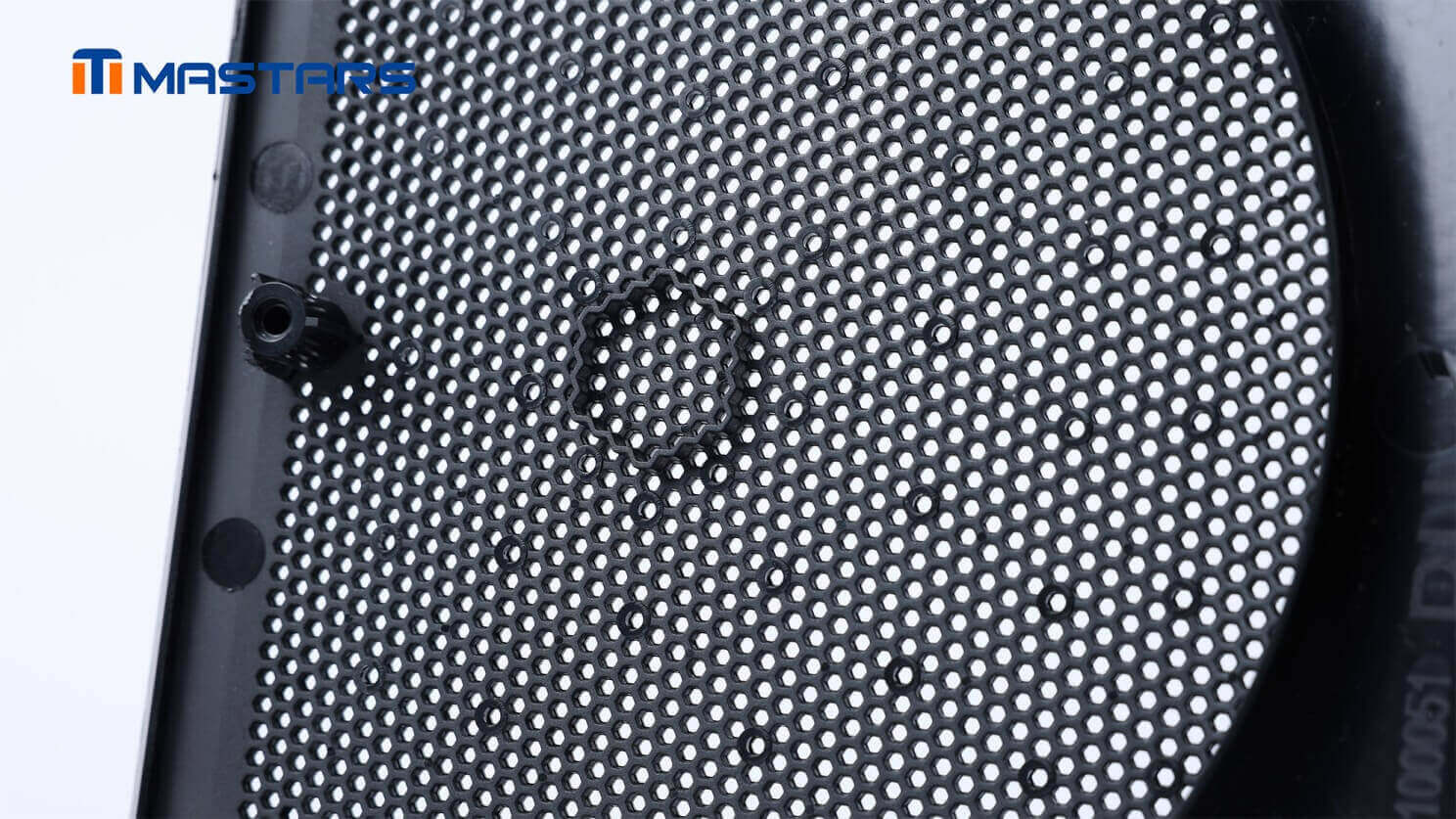
Detailed grille structure reveals dense perforations and mounting features.
For a thermoformed enclosure or panel, the same review should happen before the tooling route is finalized: identify the critical interfaces, determine which dimensions can be formed, and decide which features should be trimmed or machined afterward.
Prototype Validation Before Production Tooling
A prototype can prove that a part fits and functions without proving that the production process will reproduce it consistently. Material, sheet gauge, wall distribution, tooling, cooling, trimming, and production tolerances still need to be evaluated before the production route is locked.
For example, a prototype enclosure may confirm that a cover clears its mating components and that mounting points line up. That does not establish whether the same geometry will maintain the required wall thickness or dimensional stability after production forming.
This distinction becomes particularly important when a prototype and production part use different manufacturing processes. A 3D-printed prototype can validate form and assembly, while the eventual thermoformed or injection-molded part must be evaluated for its own material and process behavior.
Applications: Where Does Each Process Fit?
Vacuum forming is commonly used for large covers, trays, guards, packaging, and relatively simple housings. Pressure forming becomes relevant when those parts also require more defined surface features or cosmetic detail.
| Application | Process direction |
|---|---|
| Large protective covers | Vacuum forming |
| Packaging and trays | Vacuum forming |
| Industrial guards | Vacuum forming |
| Large equipment housings | Vacuum or pressure forming |
| Automotive interior panels | Pressure forming |
| Appearance-critical equipment panels | Pressure forming |
| Medical equipment covers | Vacuum or pressure forming, depending on requirements |
| Aerospace interior panels | Pressure forming, depending on requirements |
| Complex integrated housings | Injection molding or hybrid manufacturing |
The application should determine the process review, rather than assuming one thermoforming method fits every enclosure or panel.
Common Thermoforming Design Mistakes
Several recurring problems can be caught during design review:
Choosing pressure forming without a feature requirement.
The additional tooling and equipment only add value when the part needs the extra forming capability.
Specifying sheet thickness without checking the thinnest formed region.
Deep draws can change wall distribution substantially.
Treating trimming as an afterthought.
A formed shell still needs to become a dimensionally controlled component.
Ignoring draft, corner radius, and venting.
These details affect release, material distribution, and feature reproduction.
Comparing mold prices instead of finished-part cost.
Material yield, secondary machining, finishing, scrap, inspection, and assembly all belong in the comparison.
Conclusion
Vacuum forming is often sufficient for large, relatively simple parts where tooling cost and production volume are the main considerations. Pressure forming becomes relevant when surface detail, texture, lettering, ribs, or other molded features justify the additional tooling and equipment. When the design requires complex integrated features or tighter functional control, injection molding or a hybrid route should also be evaluated.
The final decision should account for the complete manufacturing route: material, mold, forming method, wall distribution, trimming, finishing, inspection, and production volume.
Need Help Choosing the Right Thermoforming Process?
Share your CAD model, material, sheet thickness, target quantity, critical dimensions, and surface requirements. Mastars can review the manufacturing route and help determine whether vacuum forming, pressure forming, injection molding, or a combination of processes makes the most sense for your part.
Rough information is fine to start.
FAQ
What is the main difference between vacuum forming and pressure forming?
Vacuum forming uses atmospheric pressure to draw a heated thermoplastic sheet against a mold. Pressure forming adds compressed air above the sheet, increasing the forming force and improving reproduction of fine mold features.
Is pressure forming more expensive?
Pressure forming normally requires more capable tooling and equipment, so its upfront cost is higher. Whether that difference matters depends on the part requirements, tooling life, secondary operations, and production volume.
Can pressure forming replace injection molding?
For some large, thin-wall, appearance-focused parts, pressure forming can be a practical alternative. Injection molding remains better suited to designs with complex integrated bosses, clips, internal geometry, and high-volume production requirements.
What materials can be used for thermoforming?
Common thermoforming materials include ABS, HIPS, PETG, polycarbonate, PMMA, PVC, polypropylene, and other thermoplastics available in sheet form. The correct grade depends on mechanical, thermal, chemical, cosmetic, and regulatory requirements.
What information should I provide for a thermoforming quote?
A CAD model is ideal, but rough information is enough to start. Provide the intended material, sheet thickness if known, target quantity, overall dimensions, critical interfaces, cosmetic surfaces, and any required holes, inserts, textures, or assembly features.
Hot Articles
Hot Tags
Stay Connected!


Manufacturing on Demand
Please fill in the following information to obtain plan details (information is confidential and not disclosed publicly), we will contact you within 24 hours, please keep your phone available!
Upload a 3D/2D model to see instant pricing, lead time, and DFM feedback.