



Injection Molding Rib Design Guidelines: How to Improve Part Stiffness and Avoid Manufacturing Defects


When a plastic part is not stiff enough, increasing wall thickness seems like the easiest solution. However, thicker sections often create new injection molding risks, including sink marks, longer cooling cycles, and uneven shrinkage.
A better approach is usually to reinforce the part where it carries load. This is where injection molding rib design becomes critical.
A well-designed rib improves stiffness without adding unnecessary material, but only when its thickness, orientation, and location follow the part's load path and are considered together with material behavior and mold requirements.
In production, a rib that looks acceptable in CAD may still cause problems after molding. Poor rib design can lead to sink marks, warpage, difficult ejection, or costly tooling changes.
This guide explains how engineers evaluate plastic ribs based on structural requirements, molding limitations, material behavior, and DFM considerations before production.
What Are Ribs Used for in Injection Molded Plastic Parts?
Ribs are thin reinforcing features added to injection molded plastic parts to increase stiffness and strength without making the entire part thicker. They are commonly used on housings, covers, structural panels, and functional components where designers need better mechanical performance while maintaining material efficiency and stable molding.
A rib works by increasing the structural moment of inertia of a part, which helps resist bending without requiring a thicker overall wall section. This makes ribs especially useful for large flat surfaces where stiffness is needed but material thickness must remain controlled.
Typical applications include:
- Reinforcing large flat plastic panels
- Supporting enclosure walls
- Improving resistance to bending and deformation
- Maintaining dimensional stability in lightweight components
- Supporting assembly features near bosses or mounting points
However, adding more ribs does not always improve the part.
A common mistake is treating ribs as a simple thickness increase. In reality, rib effectiveness depends on:
- Rib orientation
- Expected load direction
- Material properties
- Wall thickness relationship
- Mold filling conditions
- Cooling behavior
The best rib layout follows the engineering requirements of the part rather than simply filling available CAD space.
Why Increasing Wall Thickness Is Not Always the Best Solution
Increasing wall thickness and adding ribs solve similar structural problems, but they create different manufacturing results.
| Design Approach | Advantages | Potential Risks |
|---|---|---|
| Increase wall thickness | Simple geometry change, higher local strength | Sink marks, longer cooling time, higher material usage |
| Add ribs | Improves stiffness with less material | Requires careful thickness, draft, and placement control |
For injection molded parts, maintaining consistent wall thickness is usually preferred because plastic materials shrink as they cool. Thick sections cool slower than surrounding areas, creating internal stress and visible surface defects.
A rib provides reinforcement while allowing the main wall section to remain relatively uniform.
For example, a large plastic cover may feel flexible when pressed. Increasing the entire wall thickness may reduce flexibility, but it may also create sink marks on the visible surface. A properly positioned rib on the back side can improve stiffness without affecting appearance.
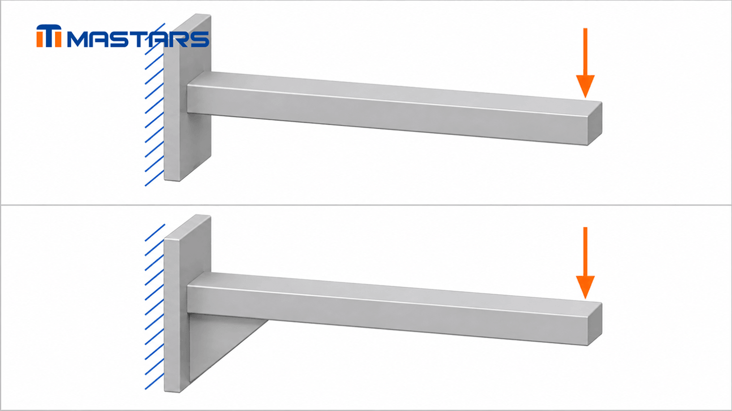
Ribbed versus unribbed structures: material is redistributed to a more effective position for resisting bending
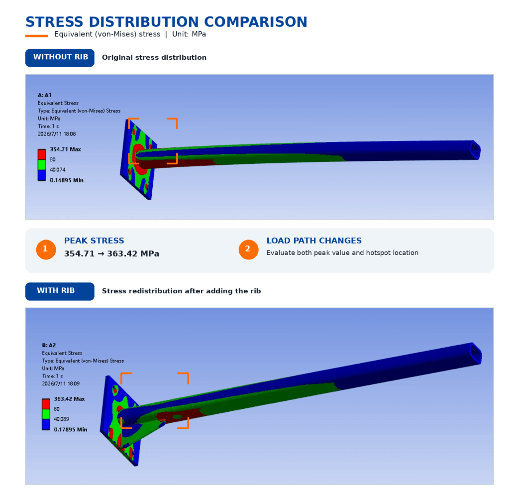
How Should Ribs Be Positioned Along the Load Path?
Rib placement should be determined by how the part carries load, not simply by available space in the CAD model. A correctly positioned rib reinforces areas under bending or stress, while a misplaced rib may add material without improving structural performance.
Engineers usually consider:
- Where the part is fixed or supported
- The direction of expected loads
- Areas with bending or flexing risk
- Connections between walls, bosses, and mounting features
For example, a rib placed perpendicular to a bending direction may provide limited improvement, while a rib aligned with the load path can significantly increase stiffness.
This is why rib design should start with functional requirements rather than copying standard dimensions directly into the CAD model.
What Is the Recommended Rib Thickness-to-Wall Thickness Ratio in Injection Molding?
A common starting guideline for injection molding rib thickness is 40% to 60% of the nominal wall thickness. However, this ratio should be treated as a design starting point rather than a fixed rule, because the final rib thickness depends on material shrinkage, cosmetic requirements, rib location, and molding conditions.
Rib thickness is one of the most important factors in plastic rib design because it directly affects cooling behavior.
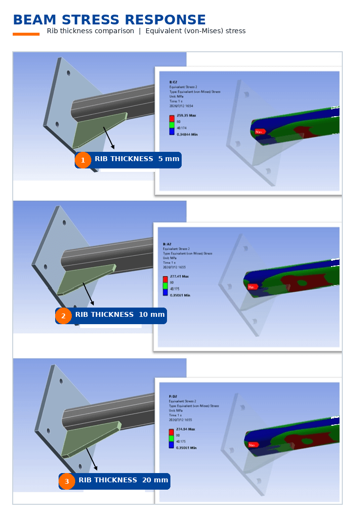
When a rib is too thick compared with the surrounding wall:
- The rib base becomes a localized thick section
- Cooling becomes uneven
- Shrinkage increases
- Sink marks may appear on the opposite surface
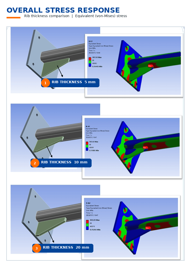
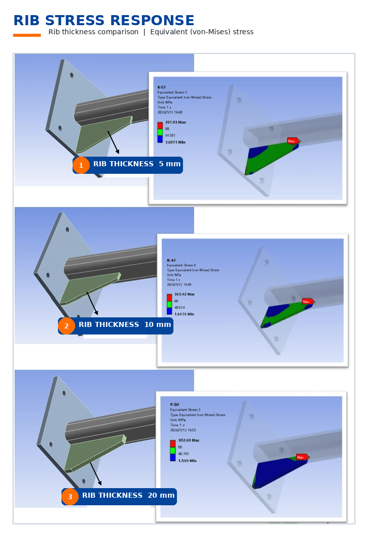
When a rib is too thin:
- Structural reinforcement may be insufficient
- Filling may become more difficult
- The rib may not provide the expected stiffness improvement
A practical starting point is:
| Design Feature | Common Starting Guideline | Main Concern |
|---|---|---|
| Rib thickness | 40%-60% of nominal wall thickness | Sink marks and cooling imbalance |
| Rib height | Usually limited by material and thickness ratio | Filling and ejection risk |
| Rib spacing | Avoid overly dense rib patterns | Cooling and mold strength |
| Rib draft | Add sufficient draft for release | Ejection stress |
A rib design that works well for a small ABS enclosure may not perform the same way on a large glass-filled nylon structural component. Material behavior, part size, surface requirements, and production volume all influence the final design decision.
How Does Rib Thickness Affect Sink Marks?
Rib thickness affects sink marks because thicker rib sections contain more plastic volume that takes longer to cool and shrink. When the surrounding material solidifies first, the shrinking rib base can pull the surface inward and create visible depressions.
Common methods to reduce rib-related sink marks include:
- Reducing rib thickness
- Increasing the number of thinner ribs instead of using one thick rib
- Maintaining consistent wall thickness
- Moving ribs away from critical cosmetic surfaces
- Reviewing rib placement with mold flow considerations
For cosmetic parts such as consumer electronics housings or medical device covers, rib design requires additional attention because even small sink marks may be unacceptable.
How Tall Can an Injection Molding Rib Be Before It Creates Problems?
The maximum practical rib height depends on material, rib thickness, mold design, and part geometry. Taller ribs can improve stiffness, but excessive height may increase filling difficulty, cooling imbalance, and ejection risks. Rib height should always be evaluated together with thickness and draft angle. More height does not always mean more stiffness. After a certain point, increasing rib height may create more molding difficulty than structural benefit.
A common mistake is increasing rib height to solve a stiffness problem without considering manufacturing limitations.
A taller rib can create:
- Longer filling paths
- Higher flow resistance
- More difficult venting
- Greater ejection friction
- Increased risk of deformation after molding
Instead of simply making ribs taller, engineers often evaluate whether the design needs:
- Additional ribs
- Different rib orientation
- A gusset structure
- A thicker transition area
- A different material grade
The correct solution depends on what the part is trying to achieve.
A rib designed for structural stiffness follows different rules from a rib used for snap-fit engagement or assembly retention.
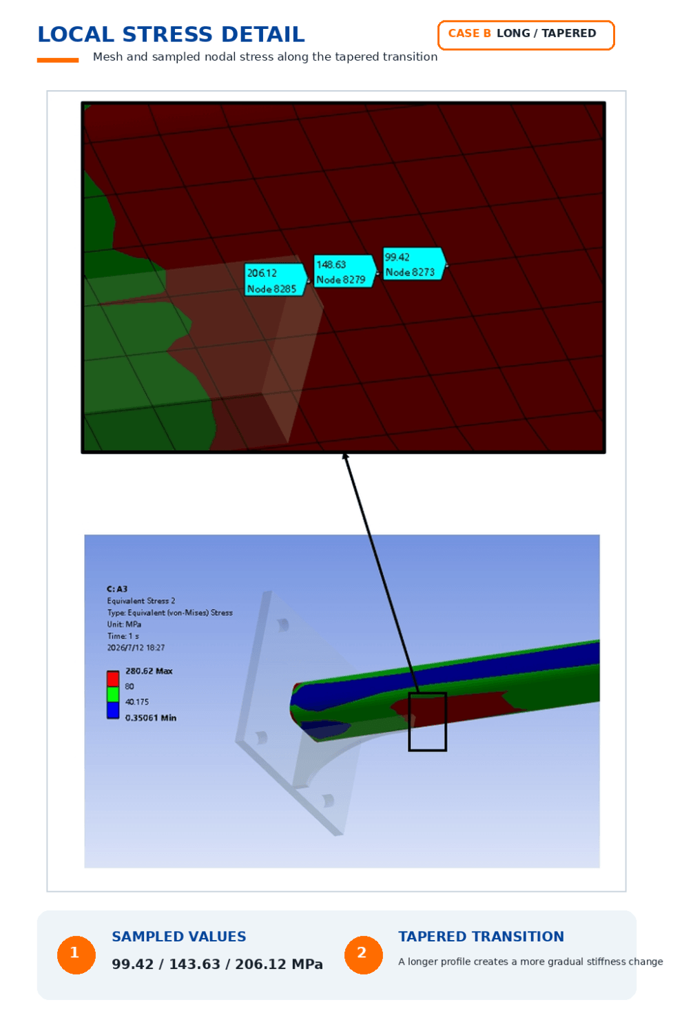
Straight Rib vs. Tapered Rib: Which Design Is Better?
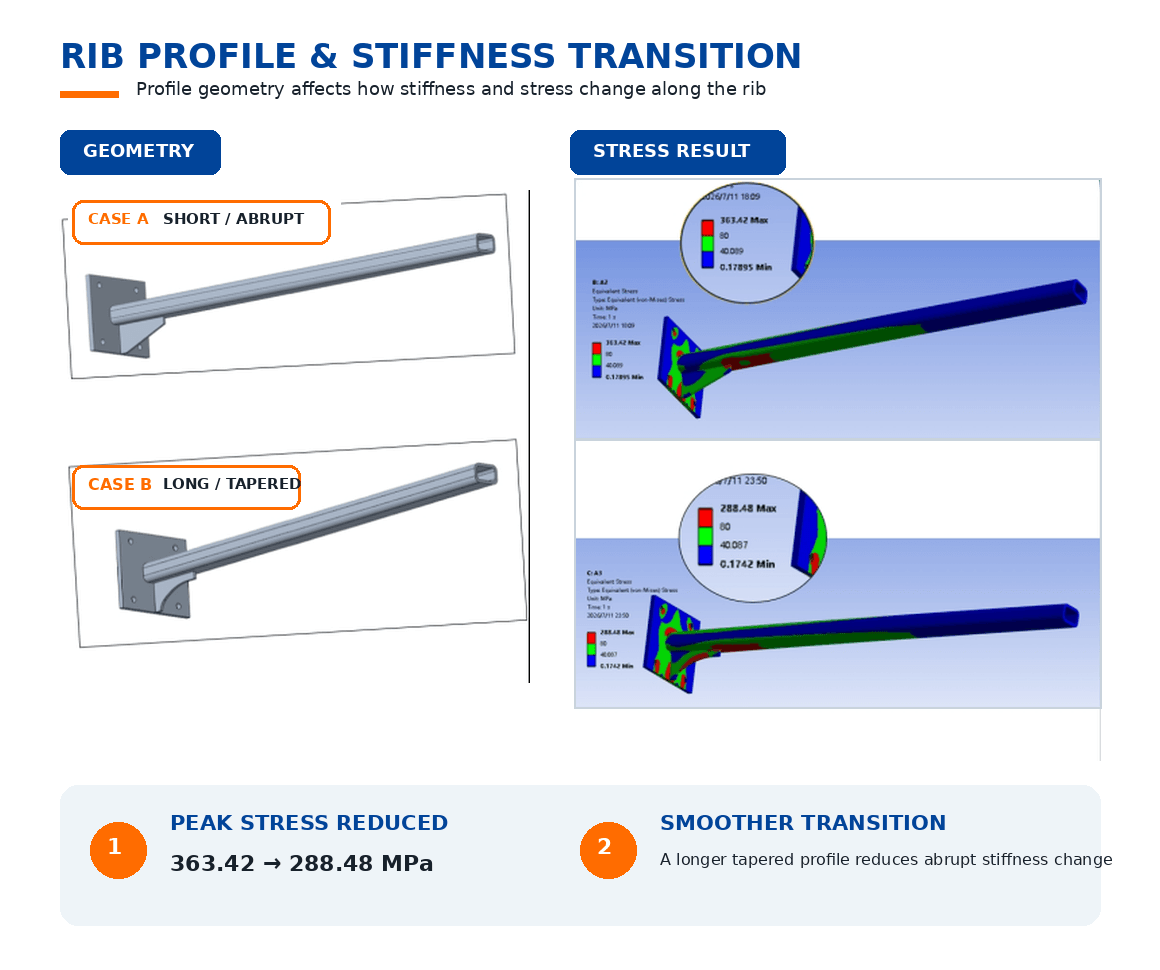
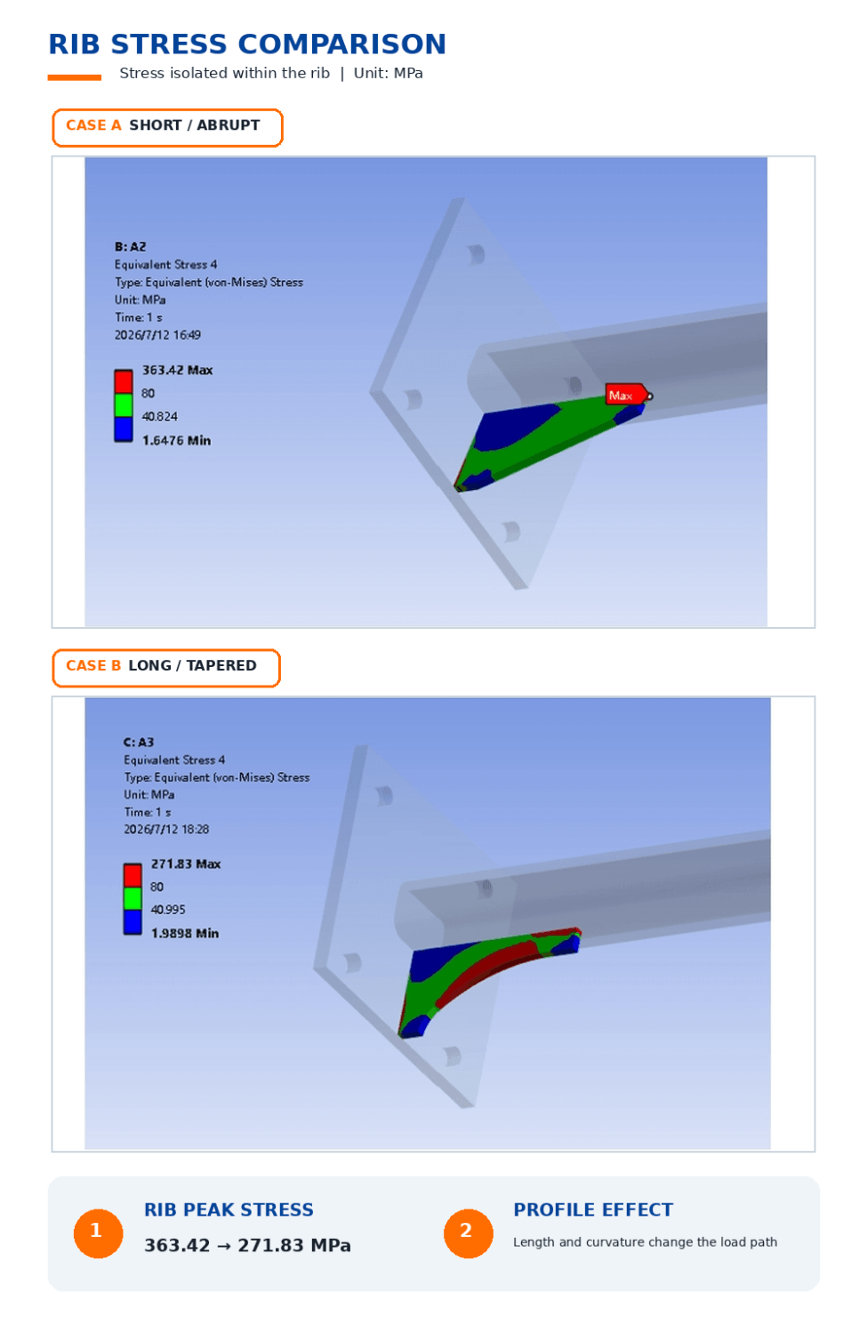
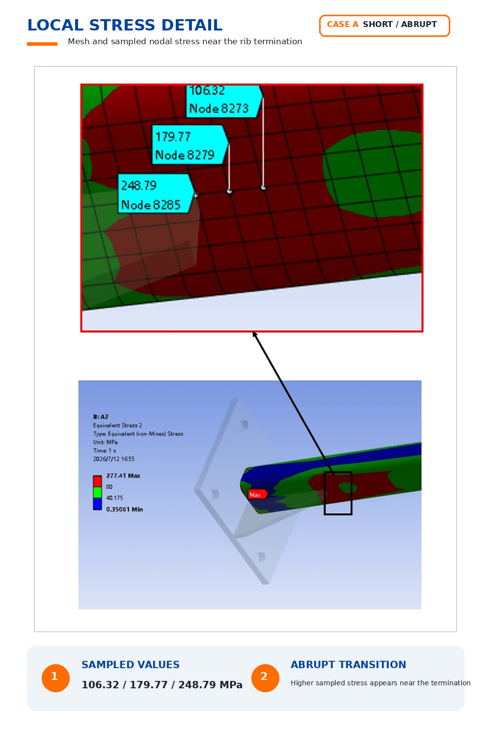
A straight rib and a tapered rib serve similar reinforcement purposes, but they behave differently during injection molding. A tapered rib can improve mold release and reduce ejection stress, while a straight rib may be easier to design and manufacture in some applications.
| Rib Type | Advantages | Design Considerations |
|---|---|---|
| Straight rib | Simple geometry, predictable design | May require more attention to filling and ejection |
| Tapered rib | Better release and smoother transitions | Requires more careful geometry control |
The best choice depends on:
- Rib height
- Material shrinkage
- Mold texture
- Ejection method
- Surface appearance requirements
For deeper ribs or textured mold surfaces, additional draft may be required to prevent part damage during ejection.
What Draft Angle and Spacing Should Injection Molding Ribs Have?
Injection molding ribs require draft angle and proper spacing to support reliable mold release and consistent cooling. Draft helps prevent the rib from sticking during ejection, while spacing reduces excessive material concentration and improves molding stability.
Rib Draft Angle Considerations
Draft angle requirements depend on:
- Rib depth
- Surface texture
- Plastic material
- Mold finish
A deeper rib usually requires more draft because the contact area between the rib and mold increases.
Insufficient draft can cause:
- Ejection marks
- Stress whitening
- Rib deformation
- Mold damage
Rib Spacing Considerations
Rib spacing affects:
- Cooling uniformity
- Material flow
- Mold strength
- Local thickness distribution
Closely packed ribs may create areas where plastic accumulates, increasing the risk of:
- Sink marks
- Warpage
- Uneven cooling
A good rib layout considers the entire part structure instead of evaluating each rib individually.
How Does Material Selection Affect Injection Molded Rib Design?
Rib design cannot be separated from material behavior because different plastics have different shrinkage rates, flow characteristics, stiffness, and warpage risks. A rib geometry that works well for one resin may create molding problems when applied to another material, especially when switching between unfilled and fiber-reinforced plastics.
Material selection affects rib design in several ways:
- Shrinkage behavior influences sink marks and dimensional accuracy
- Flow characteristics affect rib filling and weld line formation
- Mechanical properties determine how much reinforcement is actually needed
- Thermal behavior affects cooling balance and warpage risk
For example, a rib designed for ABS may not perform the same way in glass-filled nylon. The higher stiffness of reinforced materials may reduce the need for larger ribs, but fiber orientation can introduce directional shrinkage and increase warpage sensitivity.
How Do Unfilled and Filled Plastics Change Rib Design Rules?
Unfilled plastics and filled plastics require different rib design considerations because their molding behavior is different.
Unfilled Plastics
Common examples include ABS, polypropylene (PP), and polycarbonate (PC).
These materials generally have more predictable flow behavior, but rib dimensions still need to consider:
- Wall thickness consistency
- Cooling conditions
- Cosmetic surface requirements
- Part geometry
For appearance-critical parts, even a small rib-related sink mark may require design adjustments.
Glass-Filled and Mineral-Filled Plastics
Filled materials are commonly selected when a part requires:
- Higher stiffness
- Better dimensional stability
- Improved temperature resistance
However, reinforcement materials introduce additional design considerations.
Glass fibers can create:
- Directional shrinkage differences
- Flow-related mechanical variation
- Increased warpage risk
For these materials, rib orientation should be reviewed together with expected material flow direction. This is especially important for parts where dimensional accuracy or mechanical performance depends on a specific loading direction.
A rib that improves stiffness in one direction may not provide the same benefit after considering fiber orientation.
How Does Rib Placement Affect Sink Marks, Warpage, and Mold Filling?
Rib placement affects injection molding performance because ribs influence melt flow, packing pressure, and cooling behavior inside the mold. Even when rib dimensions follow common guidelines, poor placement can create defects if the rib interferes with filling balance or creates uneven shrinkage.
A rib should not be evaluated as an isolated feature.
Engineers typically review:
- Where the rib is located
- How plastic reaches the rib during filling
- Whether the rib intersects other thick sections
- Whether the rib affects cosmetic surfaces
- How the part will cool after molding
How Do Ribs Cause Sink Marks?
Ribs create sink marks when the thicker rib base cools and shrinks at a different rate than the surrounding wall.
The risk increases when:
- Rib thickness is too large
- Rib intersects with bosses or walls
- Rib is located behind a visible cosmetic surface
- Cooling is uneven
Common solutions include:
- Reducing rib thickness
- Adding more ribs with smaller dimensions
- Moving ribs away from visible surfaces
- Adjusting local wall thickness
The goal is not to eliminate ribs, but to design reinforcement without creating unnecessary thick sections.
How Does Rib Placement Affect Mold Filling?
Rib placement influences how molten plastic fills the cavity.
Poor rib placement may contribute to:
- Air traps
- Weld lines
- Short shots
- Uneven packing pressure
For example, a deep rib located at the end of a flow path may be difficult to fill because the plastic reaches the area after losing temperature and pressure.
Gate location is therefore an important factor.
A rib design that looks acceptable in CAD may still require modification after reviewing:
- Flow direction
- Gate position
- Venting strategy
- Filling balance
This is why experienced injection molding engineers review ribs together with the complete part design rather than applying isolated design rules.
How Do Ribs Influence Warpage?
Ribs influence warpage because they create differences in cooling rates and shrinkage across the part.
Warpage risk increases when:
- Rib patterns are uneven
- Rib density varies significantly
- Filled materials create directional shrinkage
- Thick rib intersections create local mass buildup
For larger plastic parts, engineers may need to consider:
- Rib layout symmetry
- Cooling balance
- Material orientation
- Mold flow results
A successful rib design improves stiffness without creating a new dimensional control problem.
Should You Use a Rib, Boss, or Gusset for Plastic Part Reinforcement?
Ribs, bosses, and gussets all reinforce injection molded plastic parts, but they solve different engineering problems. A rib is mainly used to increase panel stiffness, a boss supports fastening features, and a gusset reinforces corners or structural transitions.
Choosing the wrong reinforcement feature can increase manufacturing difficulty without improving part performance.
| Feature | Best Used For | Common Design Considerations |
|---|---|---|
| Rib | Increasing stiffness of walls and panels | Thickness, draft, sink risk |
| Boss | Screws, inserts, mounting points | Stress concentration, core design |
| Gusset | Supporting corners and joints | Local thickness, filling behavior |
Rib vs Boss: When Should You Use Each?
A rib is usually preferred when the goal is to prevent bending or flexing across a broad surface.
A boss is used when the part needs:
- Screw attachment
- Insert retention
- Alignment features
- Assembly interfaces
However, ribs and bosses often work together.
For example, a mounting boss on a thin plastic housing may require surrounding ribs or gussets to distribute assembly loads and reduce cracking risk.
The transition between these features is often more important than the individual feature itself.
Rib vs Gusset: Which Provides Better Reinforcement?
A rib and a gusset improve stiffness in different ways.
Ribs are effective for:
- Large flat surfaces
- Panel reinforcement
- Lightweight structural support
Gussets are effective for:
- Corners
- Vertical supports
- Areas with concentrated loads
In many injection molded parts, the best solution combines both.
A gusset can support the connection between a boss and a wall, while ribs can reinforce the surrounding panel.
How Should Rib Transitions, Fillets, and Rib Patterns Be Designed?
Rib transitions are critical because sharp corners and sudden thickness changes can create stress concentration and molding defects. Proper fillets, intersections, and rib patterns improve both part durability and manufacturing reliability.
The rib base is one of the highest-risk areas because it experiences:
- Mechanical stress concentration
- Material accumulation
- Cooling variation
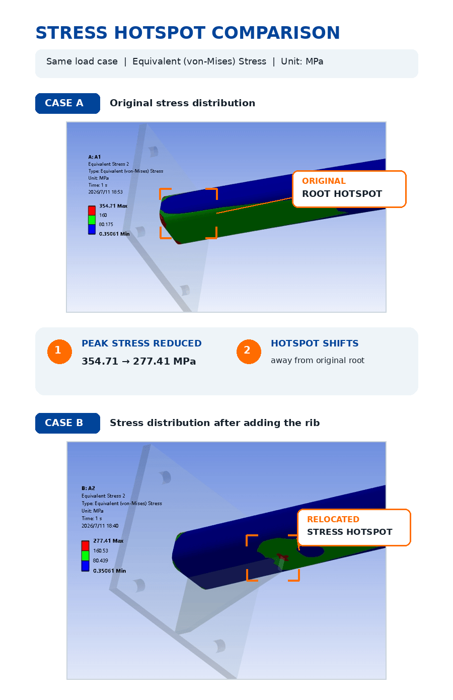
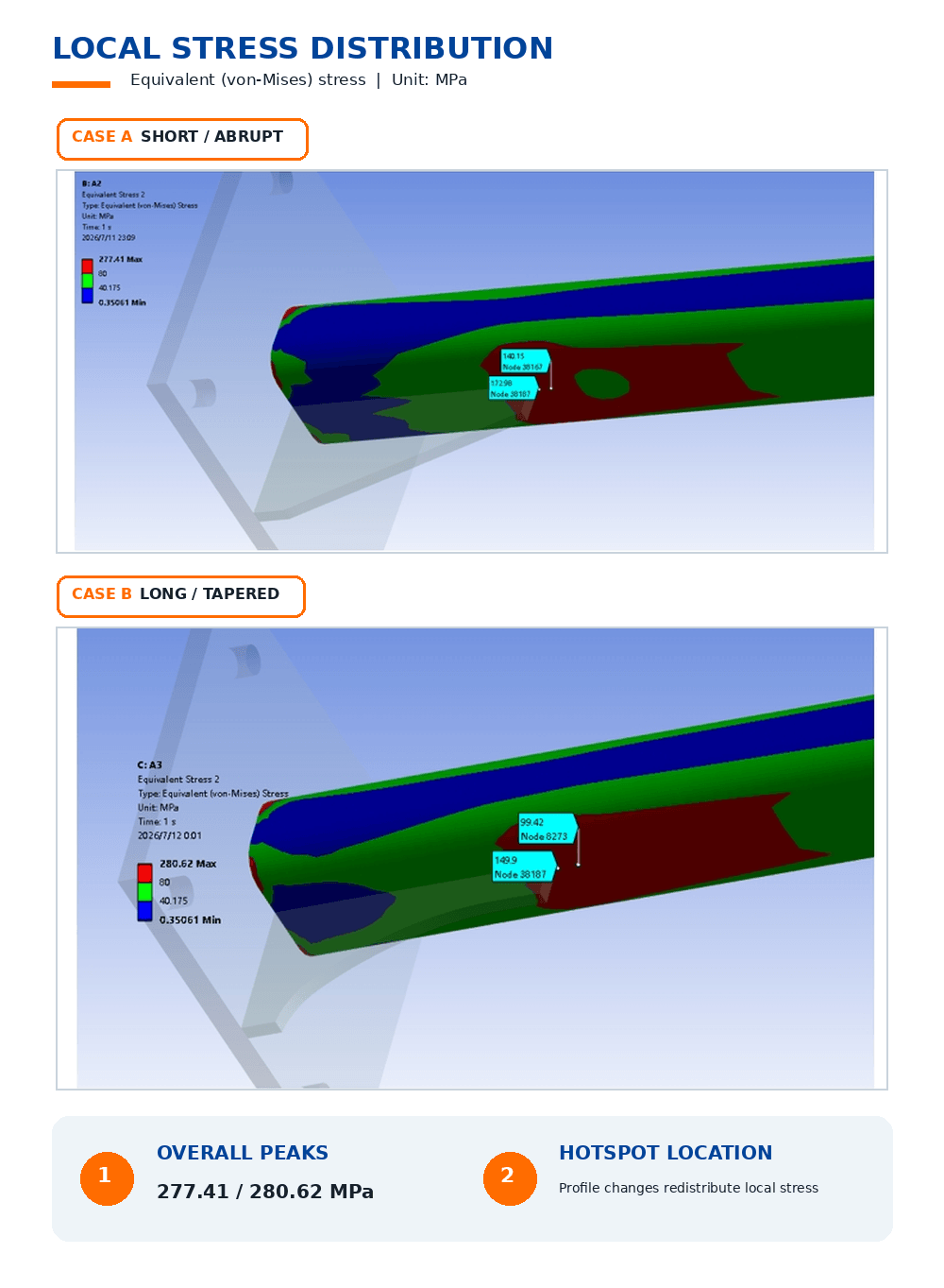
Why Are Fillets Important at Rib Bases?
Sharp rib corners can concentrate stress during loading.
Adding a suitable fillet helps:
- Distribute stress more evenly
- Improve material flow
- Reduce cracking risk
- Create smoother transitions
However, the fillet should not create an unnecessarily thick section that increases sink risk.
How Do Multiple Rib Patterns Improve Strength?
A common mistake is adding one large rib when several smaller ribs may provide better performance.
Multiple ribs can:
- Improve stiffness distribution
- Reduce local thickness
- Lower sink mark risk
- Maintain more consistent cooling
Common rib patterns include:
- Parallel ribs
- Cross ribs
- Grid structures
- Honeycomb-like reinforcement patterns
The best pattern depends on:
- Load direction
- Available space
- Appearance requirements
- Manufacturing constraints
How Do Engineers Validate Rib Design Before Injection Molding Production?
Engineers usually review rib design before tooling because many molding problems can be identified from CAD geometry, material selection, and expected process behavior. A production-ready rib design requires more than meeting basic dimension guidelines; it should also consider manufacturability, appearance requirements, dimensional stability, and production repeatability.
A rib that looks correct in a CAD model may still create problems after molding begins.
Before production, engineers typically evaluate:
- Rib geometry and thickness distribution
- Material shrinkage behavior
- Mold filling conditions
- Ejection feasibility
- Cosmetic surface risks
- Assembly requirements
Early design review helps identify potential issues before they become expensive tooling modifications.
What Should Be Checked During CAD Review of Rib Design?
CAD review is the first step in evaluating whether a rib design is suitable for injection molding. Engineers examine the relationship between ribs and the rest of the part, rather than reviewing ribs as independent features.
Key CAD review points include:
Rib Thickness
Engineers check whether rib thickness creates unnecessary mass buildup.
Questions include:
- Is the rib too thick compared with the nominal wall?
- Could it create sink marks on visible surfaces?
- Would several smaller ribs perform better?
Rib Intersections
Ribs often intersect with:
- Bosses
- Side walls
- Mounting features
- Structural supports
These intersections require careful review because they can create localized thick sections.
Potential risks include:
- Sink marks
- Uneven cooling
- Stress concentration
- Difficult mold machining
Draft and Ejection
Ribs must release from the mold properly.
Engineers review:
- Rib draft angle
- Rib depth
- Texture requirements
- Ejector locations
Insufficient draft may cause:
- Part sticking
- Ejection marks
- Deformation
- Higher mold wear
When Should Moldflow Analysis Be Used for Rib Design?
Moldflow analysis is most valuable when rib geometry, material behavior, or appearance requirements create higher molding risks. Simple parts with standard materials may only require engineering review, while complex rib networks or demanding applications may benefit from simulation before tooling.
Moldflow analysis can help evaluate:
- Filling behavior
- Weld line locations
- Air trap risks
- Pressure distribution
- Cooling balance
- Warpage prediction
Situations Where Simulation Is Worth Considering
Moldflow or similar analysis is often considered for:
Complex Rib Networks
Examples:
- Large structural housings
- Dense reinforcement patterns
- Multiple intersecting ribs
Complex geometry can make filling behavior difficult to predict.
Filled Engineering Plastics
Materials such as glass-filled nylon may require additional analysis because fiber orientation can affect:
- Shrinkage
- Mechanical performance
- Warpage direction
High Cosmetic Requirements
For visible surfaces, even small defects may be unacceptable.
Simulation can help identify risks related to:
- Sink marks
- Flow marks
- Weld lines
- Surface deformation
How Do Engineers Validate Rib Performance After Prototyping?
Prototype testing and production validation confirm whether rib design decisions achieve the required function, appearance, and dimensional performance. A successful prototype does not always mean the design is ready for mass production because molding conditions, tooling accuracy, and material behavior can introduce new variables.
Validation may include:
Functional Testing
Depending on the application, engineers may evaluate:
- Stiffness
- Load resistance
- Assembly performance
- Repeated use durability
Dimensional Inspection
Critical dimensions may include:
- Mounting locations
- Assembly interfaces
- Flatness requirements
- Overall part dimensions
For precision applications, inspection methods may include:
- CMM measurement
- Optical inspection
- Dimensional reports
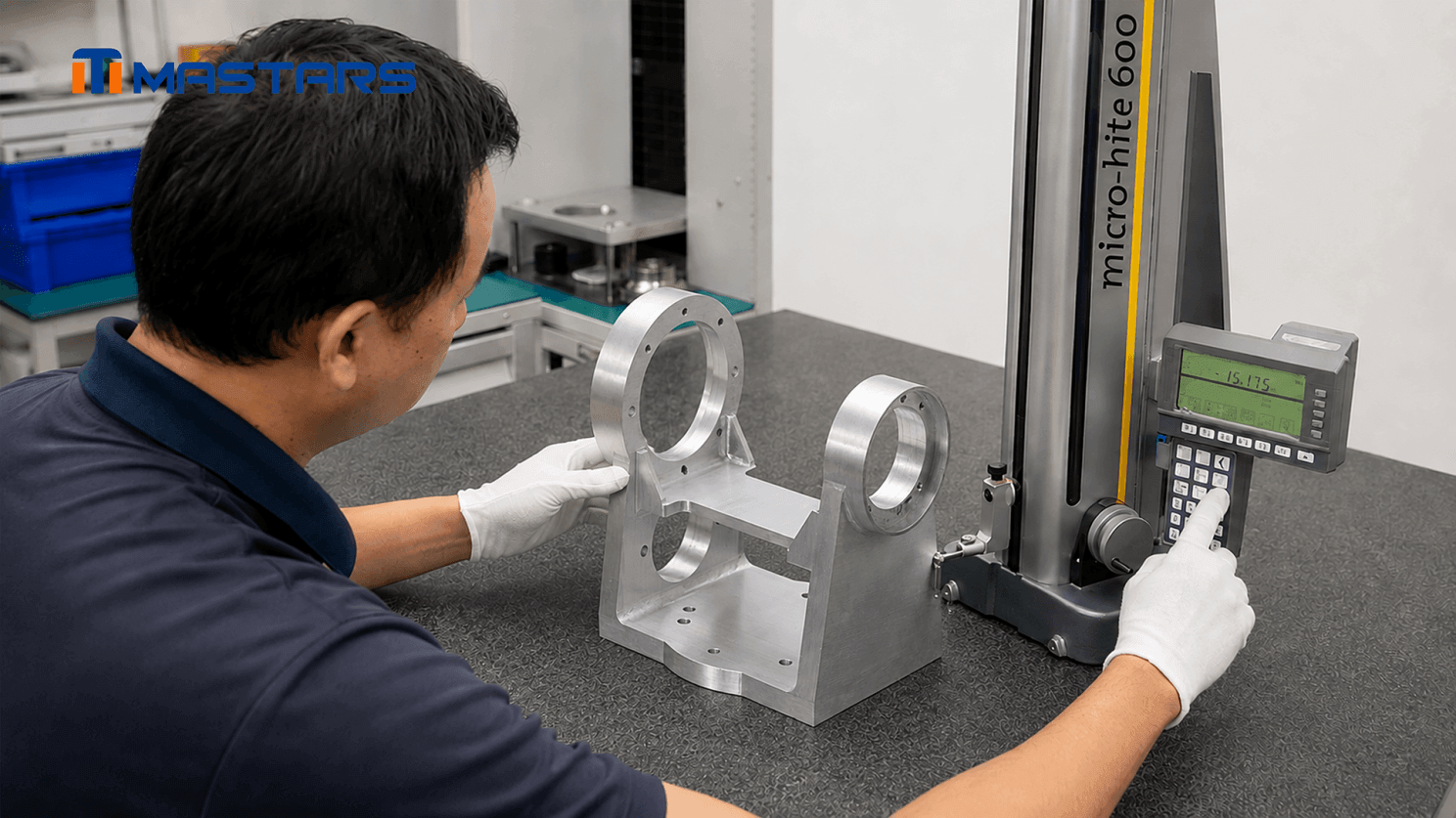
A Mastars engineer performs dimensional inspection on a CNC-machined aluminum bracket with reinforcing ribs
Production Process Review
Before scaling production, engineers evaluate:
- Process stability
- Part consistency
- Defect trends
- Material traceability
This transition is important because a prototype that proves the concept may still require design adjustments for repeatable manufacturing.
Injection Molding Rib Design Checklist Before Tooling
Before releasing an injection molded part design for tooling, engineers should confirm that rib geometry supports both part performance and production reliability. The following checklist helps identify common rib-related risks before they become tooling issues.
Structural Design
- Does the rib follow the expected load path?
- Does the rib provide meaningful stiffness improvement?
- Would multiple smaller ribs perform better than one large rib?
Geometry Review
- Is rib thickness appropriate compared with nominal wall thickness?
- Are rib height and spacing suitable for the material and mold design?
- Are rib bases properly transitioned with fillets?
- Is sufficient draft included?
Molding Risk Review
- Could the rib create sink marks?
- Could the rib interfere with filling or venting?
- Are rib intersections creating thick sections?
- Has warpage risk been considered?
Production Considerations
- Are cosmetic surfaces protected from rib-related defects?
- Are ejection requirements considered?
- Has the material behavior been reviewed?
- Has the design been evaluated for manufacturability before tooling?
A good rib design is not only strong in CAD. It must also be stable during molding.
Need a Design Review Before Tooling?
A rib design that looks acceptable in CAD may still create molding risks during production. Early engineering review can help identify potential issues related to rib thickness, material selection, shrinkage behavior, and manufacturability before tooling investment begins.
Before tooling begins, Mastars engineers can help review rib geometry, wall thickness distribution, material selection, and potential molding risks.
Share your CAD model, drawing, or initial concept with Mastars. Rough information is enough to start — critical dimensions, material requirements, and surface requirements help identify potential manufacturing risks earlier.
Frequently Asked Questions
What is the recommended rib thickness-to-wall thickness ratio for injection molding?
The common starting guideline is 40%-60% of nominal wall thickness, but there is no universal rib ratio that works for every plastic part. This range helps reduce sink marks while maintaining structural support, but the final ratio depends on material shrinkage, part geometry, cosmetic requirements, and molding conditions.
For example, a rib on a visible ABS housing may require different treatment from a rib on a glass-filled nylon structural component. Engineers should evaluate rib thickness together with material behavior and production requirements rather than applying a single fixed value.
How tall can an injection molding rib be before it causes sink marks or ejection problems?
The practical rib height depends on rib thickness, material type, draft angle, and mold design. Taller ribs can improve stiffness, but excessive height may increase filling difficulty, cooling imbalance, and ejection stress.
A deeper rib usually requires additional consideration for draft angle, venting, cooling, and mold release. Instead of simply increasing rib height, engineers often evaluate whether changing rib layout or adding additional reinforcement features provides a better manufacturing result.
What draft angle and spacing should ribs have in injection molded parts?
Rib draft angle and spacing depend on rib depth, texture requirements, material behavior, and mold design. Draft is needed to allow reliable ejection, while spacing helps prevent excessive material concentration and uneven cooling.
Designers should consider rib depth, surface texture, cosmetic requirements, cooling balance, and nearby features such as bosses and walls. The correct values are determined by the complete part design rather than the rib alone.
How does rib placement relative to the gate affect injection molding quality?
Rib placement relative to the gate can influence filling balance, weld lines, air traps, and packing behavior. A rib located at the end of a flow path may be harder to fill because the plastic reaches that area after losing temperature and pressure.
Engineers review rib placement together with gate location, flow direction, venting strategy, and part geometry. A rib design that looks acceptable in CAD may need adjustment after considering actual molding conditions.
How do filled and unfilled plastics change rib design rules?
Filled and unfilled plastics require different rib design considerations because they have different shrinkage and flow behaviors.
Unfilled materials such as ABS or PP generally have more predictable flow behavior, while glass-filled materials may introduce fiber orientation effects, directional shrinkage, and increased warpage sensitivity. Rib geometry should be adjusted based on the selected material, not transferred directly between different resin types.
How should ribs transition into bosses, gussets, and intersecting walls?
Ribs should transition smoothly into other structural features to reduce stress concentration and avoid excessive material buildup. Sharp intersections between ribs, bosses, and walls can create both mechanical and molding risks.
Engineers typically review fillet transitions, local thickness changes, cooling behavior, and assembly loads. In many plastic parts, the interaction between features is more important than the dimension of any single feature.
What are crush ribs and snap-fit ribs, and how are they different from structural ribs?
Crush ribs and snap-fit ribs serve different purposes from structural ribs. Structural ribs mainly increase stiffness, while functional ribs are designed for controlled deformation, retention, or assembly performance.
Examples include snap-fit ribs designed for flexible engagement and repeated assembly, crush ribs designed for controlled interference and component retention, and structural ribs designed for stiffness and load support. These features require different design considerations and should not use the same geometry rules.
Can Mastars help review my rib design before injection molding production?
Yes. Mastars can review plastic part designs before production to identify potential risks related to rib geometry, wall thickness, material selection, and injection molding feasibility.
Providing CAD files, drawings, or even early concepts helps engineers evaluate areas such as rib thickness, wall consistency, sink mark risks, moldability, and production considerations. Early design review can help reduce unnecessary tooling changes and improve the transition from design to manufacturing.
Hot Articles
Hot Tags
Stay Connected!


Manufacturing on Demand
Please fill in the following information to obtain plan details (information is confidential and not disclosed publicly), we will contact you within 24 hours, please keep your phone available!
Upload a 3D/2D model to see instant pricing, lead time, and DFM feedback.