



Metal Injection Molding vs Die Casting: Cost, Geometry & Production Volume


Choosing between metal injection molding (MIM) and die casting affects more than the shape of a metal part. The wrong process can lock a project into unsuitable materials, expensive tooling changes, or secondary machining that was not included in the original cost estimate. A part that looks acceptable after forming can also fail when its holes, threads, or locating surfaces must align during assembly.
MIM is a strong candidate for small, intricate components made from suitable powder alloys, including certain stainless steels. High-pressure die casting is generally the more direct route for compatible aluminum, zinc, and magnesium alloy parts. Material requirements narrow the options first; geometry, critical dimensions, quality risks, and production economics determine the final choice.
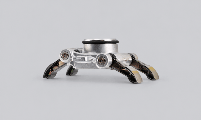
| Comparison factor | Metal injection molding (MIM) | High-pressure die casting |
|---|---|---|
| Typical materials | Stainless steels, low-alloy steels, and other qualified powder alloys | Aluminum, zinc, and magnesium die-casting alloys |
| Typical part designs | Small, intricate components with complex features | Housings, brackets, covers, and other parts suited to die filling |
| Main dimensional concern | Shrinkage and distortion during debinding and sintering | Filling, solidification, shrinkage, and warpage |
| Key quality risks | Density variation, incomplete sintering, dimensional distortion | Gas or shrinkage porosity, cold shuts, and other casting defects |
| Common secondary operations | Sizing, machining, heat treatment, or finishing | Trimming, machining, threading, and finishing |
| Major cost drivers | Tooling, feedstock, debinding, sintering, yield, and finishing | Tooling, casting cycle, alloy, yield, machining, and inspection |
| First design question | Can the part sinter to the required geometry and material properties? | Can the alloy fill and solidify without unacceptable defects? |
The sections below focus on the factors that can change the decision: material compatibility, geometry and tolerances, process-specific quality risks, and the cost of delivering accepted parts.
How Do MIM and Die Casting Produce Metal Parts?
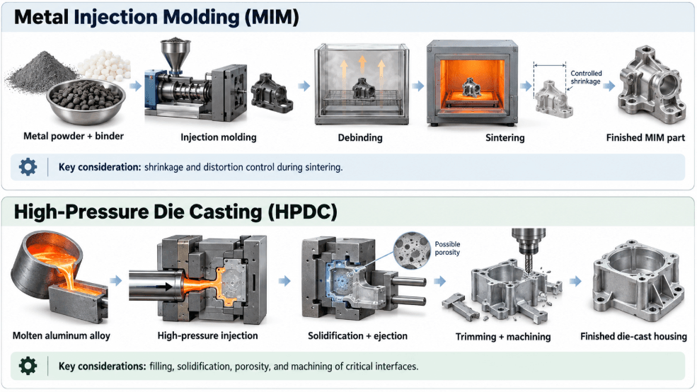
MIM forms a component through molding, debinding, and sintering. High-pressure die casting forms one by solidifying molten alloy inside a metal die. Because the metal develops differently in each process, the two routes have different dimensional risks, defect mechanisms, and finishing requirements.
Metal injection molding: From feedstock to sintered part
MIM starts with fine metal powder blended with a binder to create an injectable feedstock. After molding, the green part contains both metal powder and binder. Debinding removes the binder, and sintering bonds the metal particles at elevated temperature while the component undergoes planned shrinkage.
That shrinkage must be accounted for in tool design and validated on the finished part. Features that look correct in the green part can move or distort during sintering. Depending on the design and material system, the finished component may also require sizing, machining, heat treatment, or surface finishing.
High-pressure die casting: Filling and solidifying the die
High-pressure die casting injects molten metal into a metal die at high speed and pressure. The alloy fills the cavity, solidifies, and is ejected. Runners, gates, and flash are removed as required. The process is widely used for compatible aluminum, zinc, and magnesium alloys.
Filling and solidification govern many of its manufacturing risks. Thin sections may fill inconsistently, local hot spots can contribute to shrinkage defects, and trapped gas can leave internal porosity. Cooling and ejection can also affect dimensional stability.
A cast part may have most of its external shape established, but bores, threads, sealing faces, and mounting interfaces may still need machining. This distinction matters when a component must fit into an assembly: the cast geometry establishes the starting shape, while selected machined features may control the final fit.
Which Materials Suit MIM, and Which Suit Die Casting?
Material selection is often the quickest way to narrow the process choice. MIM is commonly considered for small, complex parts requiring suitable steels or other qualified powder alloys. Die casting is a more direct starting point for compatible aluminum, zinc, and magnesium alloys. The specified grade and finished material condition matter as much as the process name.
When should MIM materials be considered?
MIM is used for components requiring materials such as 316L stainless steel, 17-4 PH stainless steel, and other qualified powder alloys. Their availability and finished properties depend on the feedstock and processing route, including any subsequent heat treatment. A grade designation alone does not guarantee a specific strength, corrosion resistance, hardness, or density.
- 316L stainless steel: Commonly selected for corrosion resistance. Confirm suitability against the actual service environment and finished material condition.
- 17-4 PH stainless steel: Used where strength and corrosion resistance are both important. Heat-treatment condition affects its mechanical properties.
- Other powder alloys: Can address specialized requirements, but the available material system must meet the part's property and processing needs.
Specify the required properties alongside the alloy designation. For load-bearing components, moving interfaces, or parts exposed to corrosive environments, identify the relevant mechanical or environmental requirements and how they will be verified.
When is die casting the better material route?
Die casting is generally the more direct choice for compatible aluminum, zinc, and magnesium alloys. These materials are not interchangeable; they differ in density, mechanical behavior, corrosion characteristics, and manufacturing considerations.
| Alloy family | Why designers use it | What to evaluate |
|---|---|---|
| Aluminum die-casting alloys | Relatively low weight and useful structural properties | Strength requirements, section thickness, porosity risk, corrosion exposure, and machining |
| Zinc die-casting alloys | Good detail reproduction in suitable geometries | Part size, weight, service loads, operating environment, and finishing |
| Magnesium die-casting alloys | Low weight for applications suited to the alloy | Mechanical loading, corrosion protection, handling, and application-specific safety requirements |
Compare the required properties with the proposed finished material—not generic claims about MIM or die casting. A stainless-steel MIM component and an aluminum die casting differ in both process and material. Any strength comparison needs to account for the alloy, heat treatment, test method, and loading conditions.
How Do Geometry, Wall Thickness, and Tolerances Affect the Choice?
Both processes can produce complex shapes, but their design constraints differ. MIM must accommodate debinding and sintering, including shrinkage and distortion. Die casting must accommodate metal flow, solidification, draft, and ejection, along with the risk of porosity. The design must suit the process while meeting the part's functional requirements.
Which part geometries favor each process?
MIM is particularly useful for small components with intricate features that would otherwise require several machining operations or separate parts. Die casting is commonly used for housings, covers, and brackets whose geometry suits die filling and release. Neither process makes every undercut, thin wall, or internal feature automatically manufacturable.
Review the CAD model for more than its external shape:
- Wall thickness: Abrupt changes can complicate filling or contribute to uneven sintering behavior. Review transitions as well as nominal thickness.
- Ribs and bosses: Their thickness and connection to the main wall can affect filling, cooling, or dimensional stability.
- Undercuts and internal features: Determine whether they require slides, special tooling, secondary machining, or a different process.
- Holes and threads: Decide which features can be formed and which should be machined.
- Datum and locating surfaces: Establish how the part will be held for inspection and how functional features relate to those datums.
A bracket with mounting holes that must align with a mating component illustrates why the datum scheme matters. If the drawing controls each hole's size but not its position relative to the locating surfaces, the individual features could pass inspection while the assembly still fails to align. The process and inspection plan need to control the functional relationship, not just the dimensions of isolated features.
How should tolerances be specified for MIM and die-cast parts?
Start with the dimensions that control fit, movement, sealing, or alignment. Apply tighter tolerances where function requires them rather than assigning a uniformly tight tolerance to every surface. Both processes can require secondary machining for critical features, and the drawing should distinguish dimensions formed by the tool from those established during later operations.
Separate three types of dimensions in the drawing and manufacturing plan:
- As-formed dimensions: Features produced directly by molding or casting. Their variation is influenced by tooling, material behavior, and process control.
- Machined dimensions: Features created or finished in a secondary operation. Machining provides another route to dimensional control but adds setup, fixturing, cycle time, and inspection.
- Functional relationships: Distances, positions, and orientations between features that determine fit and performance in the assembly.
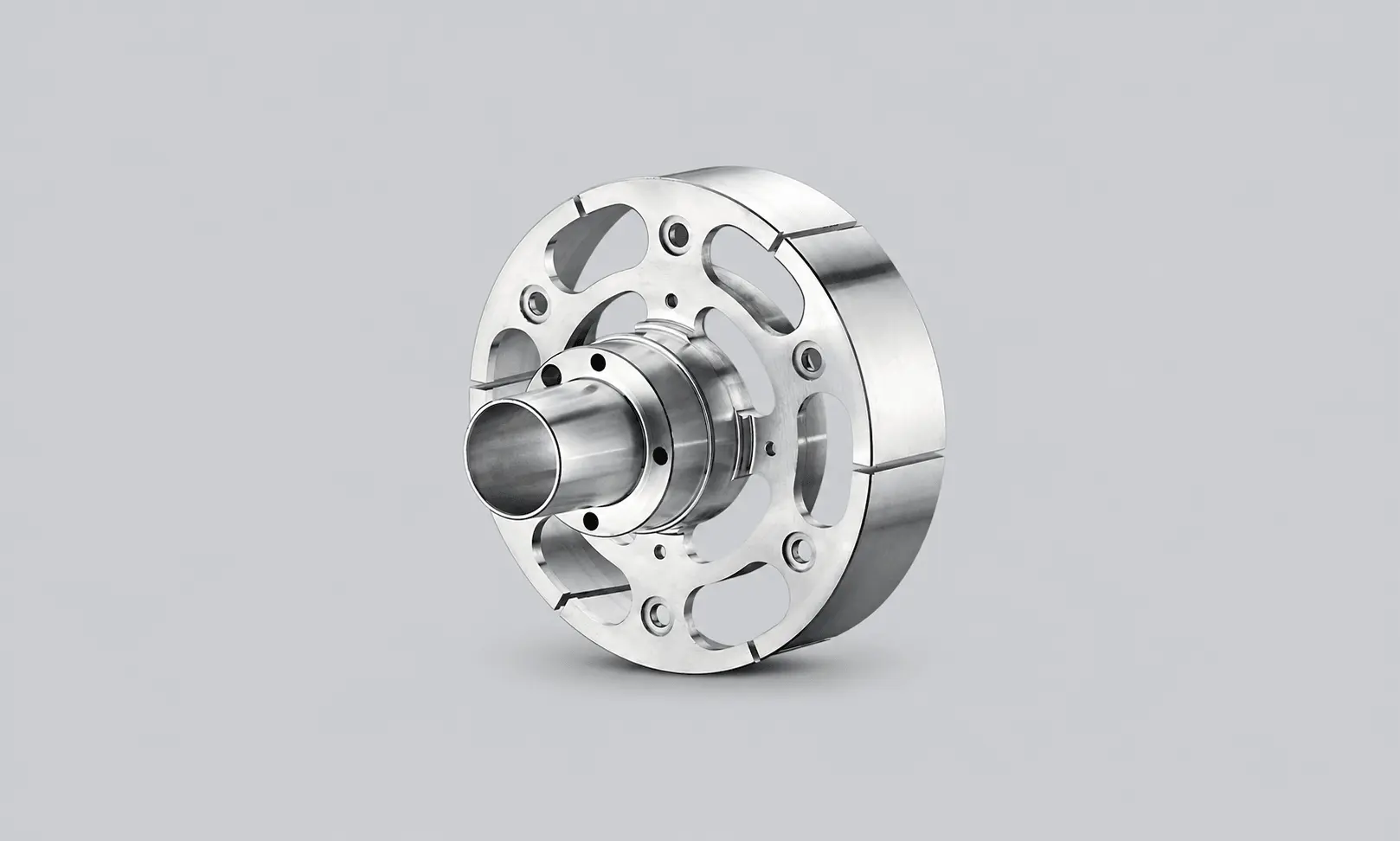
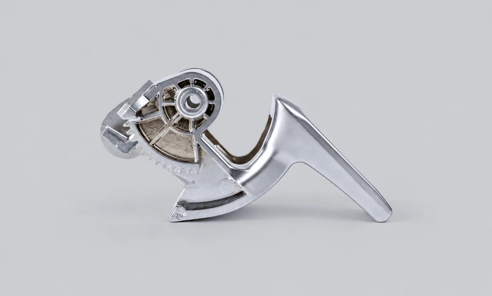
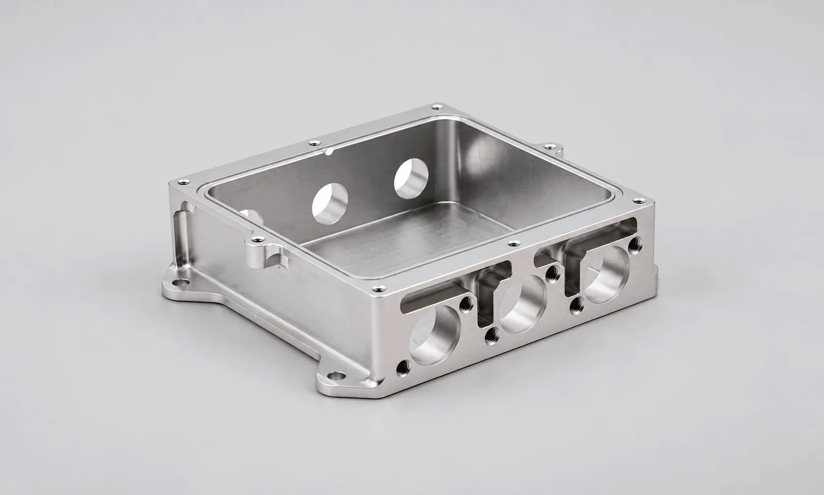
This distinction also guides the manufacturing route for die-cast components. In Mastars' stage-lighting Pan Shaft project, the process includes tooling, die casting, trimming, secondary machining, threading, and dimensional verification around assembly interfaces. The practical lesson is that the cast shape and the final assembly-critical features need different levels of control. Threaded mounting points and locating interfaces must be considered alongside the operations that establish them.
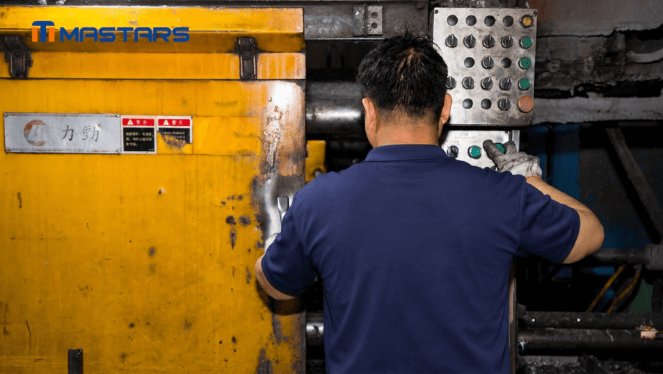
Controlled die-casting operation helps maintain consistent part geometry for downstream processing and assembly.
For a typical design, a housing may need a machined bearing bore and a mounting-hole pattern located relative to that bore. Controlling the bore diameter alone will not ensure that its axis is correctly positioned relative to the mounting pattern. The datum scheme, machining setup, and inspection method must control that relationship.
Surface finishing also affects dimensional planning. Coatings can change dimensions, while cosmetic finishing may be unsuitable for precision interfaces. Identify bearing seats, sealing faces, threaded holes, and visible surfaces separately. GD&T should reflect how the component is located and constrained in the actual assembly.
What Quality Risks Should You Compare?
MIM and die casting have different primary quality risks. MIM requires control of debinding, sintering, shrinkage, and final material condition. Die casting requires control of filling and solidification, including gas and shrinkage porosity. Inspection should target the defects and dimensional characteristics that could affect the part in service.
MIM: Shrinkage, distortion, and material consistency
During MIM sintering, the component shrinks as the metal particles bond and densify. The amount and uniformity of shrinkage depend on the material system and process conditions. Distortion may appear as a positional error, a warped surface, or a feature that no longer meets its fit requirement, even when the mold cavity was made correctly.
Validate the finished, sintered component rather than relying on the green part's dimensions. Measure the features that control assembly and function. Where material properties are critical, dimensional inspection alone is insufficient; the specification should state the relevant material requirements and verification method.
A successful prototype does not automatically establish production readiness. The process must continue to produce parts that meet the requirements across the intended production run.
Die casting: Porosity and application-specific acceptance
Porosity deserves particular attention when a die-cast component must retain pressure, withstand fatigue loading, or provide a reliable sealing interface. Gas-related and shrinkage-related defects can have different causes and distributions, so visual inspection of the outer surface cannot establish that the internal structure is acceptable.
Set acceptance criteria according to the part's function. Pressure-retaining components need defined leak-test methods and limits. Fatigue-loaded components may require additional evaluation of internal defects. A noncritical cover and a fluid-handling housing should not automatically share the same acceptance criteria.
For a production project, define the required inspection or validation method in terms of the actual service conditions, rather than relying on a general request for “high quality.”
How Do Tooling, Production Volume, and Total Cost Compare?
Both MIM and die casting require dedicated tooling and process development. Their economics depend on tooling investment, production quantity, process yield, and the operations needed to deliver conforming parts. Compare complete manufacturing routes rather than the molding or casting price alone.
What drives tooling and production costs?
MIM costs include the mold, feedstock, debinding, sintering, yield, and any required sizing or finishing. Die-casting costs include the die, casting cycle, alloy, yield, trimming, machining, and inspection. Cavity count affects output and cost, but a higher cavity count is not automatically better if it complicates filling, process stability, or tool maintenance.
Design changes also carry different costs at different stages. Moving a mounting hole or changing a wall may affect the tool, the manufacturing process, or both. Resolve major questions about interfaces, material, critical dimensions, and inspection before committing to production tooling.
How should cost per accepted part be compared?
Use the same drawing revision, material specification, quantity, and acceptance criteria when comparing quotations. Include every operation needed to deliver a usable part.
Total Cost = Tooling + Production + Post-processing + Inspection + Logistics
Cost per Accepted Part = Total Cost ÷ Accepted Quantity
A die-cast housing may need a machined bearing bore, threaded mounting holes, and inspection of the relationship between those features. An MIM component may require sizing or machining of selected interfaces, plus dimensional checks after sintering. If one quote includes these operations and the other prices only the as-formed part, the unit prices are not directly comparable.
Volume matters, but there is no universal break-even quantity for MIM, die casting, and machining. Compare the initial order, annual demand, expected design revisions, tooling commitment, and lifetime volume. If the design is still changing, CNC machining may be a practical way to validate it before investing in dedicated tooling.
A Practical Process-Selection Framework
Choose MIM for small, intricate components that suit an available powder alloy. Choose die casting when a compatible aluminum, zinc, or magnesium alloy meets the design requirements and the geometry suits die filling and ejection. For low quantities or frequent design changes, evaluate CNC machining before committing to dedicated tooling.
| Main requirement | Process to evaluate first | Reason |
|---|---|---|
| Small, intricate metal part requiring a suitable stainless or specialty powder alloy | MIM | Can consolidate complex geometry into a molded metal component |
| Aluminum, zinc, or magnesium part suited to high-pressure die casting | Die casting | Direct route for compatible alloys and suitable production volumes |
| Low-volume parts or frequent design revisions | CNC machining | Avoids immediate commitment to dedicated molding or casting tooling |
| Geometry or alloy unsuitable for MIM or die casting | Investment casting or another suitable process | May accommodate different material and geometry requirements |
CNC machining is useful when dimensions are likely to change or quantities do not justify dedicated tooling. Its limitations include material removal, machining time, and the cost of producing intricate internal features.
Investment casting may suit alloys or geometries that are not a good fit for die casting, but it has its own tooling, finishing, and dimensional considerations. It is not an automatic substitute for either process. The choice should follow the actual drawing, material requirements, critical interfaces, and production quantity.
A practical selection sequence is:
- Screen by material. Eliminate processes that cannot provide the required alloy or material condition.
- Review functional geometry. Identify critical interfaces, wall transitions, holes, threads, and undercuts.
- Set acceptance requirements. Define the dimensions, material properties, surface conditions, and tests that determine whether the part is acceptable.
- Compare manufacturing routes. Include tooling, secondary operations, inspection, and expected production volume.
- Validate the selected process. Check representative parts against the drawing and functional requirements before moving into repeat production.
Conclusion: Choose the Process That Fits the Part
MIM is a candidate for small, intricate components made from suitable powder alloys. Die casting is generally the more direct route for compatible aluminum, zinc, and magnesium parts. The decision comes down to material requirements, geometry, dimensional control, defect risks, and production economics—not a universal ranking of the two processes.
Identify the critical interfaces, decide which features need secondary machining, and define how the finished part will be accepted. These requirements give suppliers a clear basis for recommending a suitable manufacturing route and preparing a comparable quotation.
Send Mastars your CAD model or engineering drawing, target material, expected quantity, and critical dimensions or GD&T requirements. Include surface-finish requirements and any functional tests, such as pressure or leak testing, that affect acceptance.
If the design is still in development, preliminary information is fine to start. Flag the interfaces and operating conditions that matter most so the available manufacturing routes can be assessed against the actual application.
Frequently Asked Questions
Is metal injection molding the same as die casting?
No. MIM injects metal powder mixed with a binder into a mold, then removes the binder and sinters the part. Die casting injects molten alloy into a metal die and solidifies it under pressure. The processes use different material systems and have different dimensional and quality risks.
Is MIM stronger than die casting?
Not inherently. Strength depends on the alloy, material condition, geometry, and test method. Compare the finished materials against the component's actual mechanical requirements rather than assuming one process produces stronger parts.
Is MIM cheaper than die casting?
Neither is automatically cheaper. Compare quotations for the same quantity, drawing revision, material specification, and acceptance criteria, including the secondary operations and inspection needed to deliver conforming parts.
What tolerances can MIM and die casting achieve?
There is no single tolerance that applies to every part. Feature geometry, material behavior, tooling, process control, and measurement conditions all matter. Identify critical dimensions and GD&T on the drawing, and determine whether features controlling fit, alignment, or sealing need secondary machining.
What should be sent to a manufacturer to compare MIM and die casting?
Start with a CAD model or engineering drawing, target material, expected quantity, critical dimensions, GD&T, and surface-finish requirements. Include relevant service conditions, such as mechanical loads, corrosion exposure, or sealing requirements. If some details are not finalized, send the information available and identify the open questions.
Hot Articles
Hot Tags
Stay Connected!


Manufacturing on Demand
Please fill in the following information to obtain plan details (information is confidential and not disclosed publicly), we will contact you within 24 hours, please keep your phone available!
Upload a 3D/2D model to see instant pricing, lead time, and DFM feedback.