



Die Casting vs. Plastic Injection Molding: How to Choose the Right Process


A tooling quote can look attractive until the rest of the manufacturing route is considered. The material may drive the choice more than the mold price. A housing that needs to dissipate heat or provide structural stiffness may justify a metal process. But the same general enclosure shape does not automatically require metal. If an engineering plastic can meet the load, temperature, and dimensional requirements, injection molding may reduce weight and simplify cosmetic integration.
That is where die casting vs. injection molding becomes a real engineering decision. Die casting is generally evaluated when the part needs to perform as metal. Plastic injection molding becomes attractive when a polymer can meet the mechanical, thermal, environmental, and dimensional requirements without the added weight or material constraints of metal.
The comparison becomes clearer when the complete manufacturing route is considered, including tooling, production volume, tolerances, machining, finishing, and inspection.
| Decision factor | Die Casting | Plastic Injection Molding |
|---|---|---|
| Material family | Aluminum, zinc, magnesium and other suitable non-ferrous alloys | Thermoplastics, elastomers, and engineering polymers |
| Best suited to | Metal strength, heat dissipation, conductivity, structural function | Low weight, insulation, color, texture, complex polymer features |
| Tooling focus | Thermal cycling, erosion, heat removal, metal flow | Shrinkage, flow balance, surface replication, part release |
| Typical secondary work | Trimming, CNC machining, deburring, finishing, assembly | Degating, finishing, printing, coating, assembly |
| Main design concerns | Flow, porosity, draft, thermal cycling, machined features | Wall thickness, shrinkage, warpage, sink marks, cosmetic quality |
| Main decision trigger | The part needs to perform as metal | A polymer can meet the functional requirements |
The sections below focus on the factors that usually change the manufacturing route: material, mold design, production volume, cost, geometry, tolerances, and secondary operations.
What Is the Difference Between Die Casting and Injection Molding?
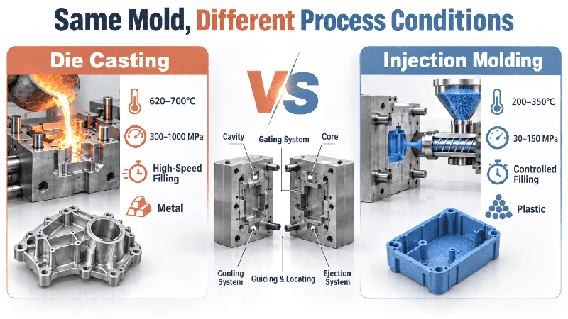
Die casting and plastic injection molding both fill a closed mold and release a solidified part, but the forming conditions are very different. Die casting uses molten metal under high pressure and rapid filling, while injection molding processes molten polymer and depends heavily on controlled cooling, shrinkage, and mold temperature.
Both processes use cavities, cores, gates, cooling systems, vents, and ejection features. They also require decisions about draft, wall thickness, parting lines, transitions, and critical dimensions.
The biggest differences appear during filling and cooling.
Die casting typically involves metal temperatures of approximately 620–700°C and pressures in the range of 300–1000 MPa, with filling potentially occurring within about 0.01–0.1 seconds. Injection molding generally operates at lower temperatures and pressures, with typical process ranges around 200–350°C and 30–150 MPa. These figures are process-level references, not universal design limits, and the exact values depend on alloy, resin, machine, part geometry, and process conditions.
Those differences in temperature, pressure, and filling behavior carry directly into the tooling design.
Start With the Material Requirement
Material selection should come before the tooling comparison. When a part needs the stiffness, heat dissipation, conductivity, or EMI shielding associated with a metal structure, die casting is a logical process to investigate. When an engineering polymer can meet those requirements, injection molding may reduce weight and provide more options for insulation and appearance.
When Does Die Casting Make Sense?
Die casting is worth considering when the component has to provide a meaningful metal function. Aluminum, zinc, and magnesium alloys can support compact structural designs while providing properties that are difficult to reproduce with conventional plastics.
Typical applications include:
- Structural housings and brackets
- Heat-dissipating components
- Conductive or EMI-shielding enclosures
- Components exposed to elevated temperatures
- Metal interfaces subject to wear
- Rigid components where section stiffness matters
- Housings with integrated ribs, bosses, mounting features, and apertures
For these parts, the casting can provide most of the geometry, while CNC machining finishes features that affect assembly.
Mastars provides custom die casting services for aluminum and zinc die casting, with secondary operations available when cast geometry alone is not enough for the required functional interfaces.
A useful distinction is between cast geometry and functional geometry. The outer body may be produced close to its final shape, while a threaded hole, locating bore, or sealing face receives additional machining.
When Is Plastic Injection Molding a Better Fit?
Plastic injection molding becomes attractive when an engineering polymer can handle the part’s mechanical and environmental requirements. Lower weight is one reason. Electrical insulation, corrosion resistance, color, texture, transparency, and integrated cosmetic features can also make a polymer the better material choice.
Common applications include:
- Lightweight housings
- Electrically insulated components
- Corrosion-resistant parts
- Transparent or translucent covers
- Cosmetic housings with integrated color and texture
- Flexible sections
- Insert-molded components
- Overmolded assemblies
Materials such as ABS, PP, PC, PA, POM, TPU, PEEK, and other engineering polymers behave quite differently. Stiffness, creep, impact resistance, temperature exposure, chemical resistance, moisture absorption, and dimensional stability all need to be considered.
Mastars’ plastic injection molding services cover a range of thermoplastics and engineering plastics, with DFM and inspection incorporated into the manufacturing process.
“Plastic” is not a single material category. A material that works for a cosmetic cover may be a poor choice for a high-temperature structural bracket.
Material Behavior and Mold Design
Changing from metal to polymer affects the tooling design, particularly around venting, cooling, cavity finish, and ejection. The mold has to accommodate the material’s flow and cooling behavior, as well as how the finished part releases from the cavity.
Mold Steel Depends on the Process
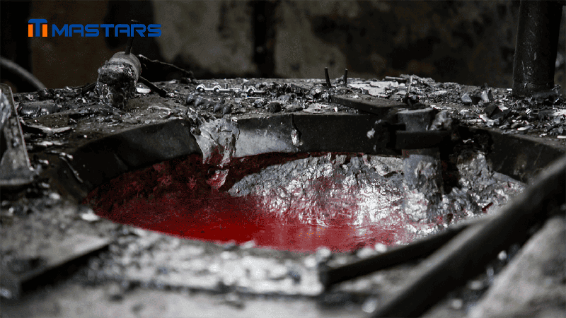
Die-casting dies repeatedly encounter molten metal, high pressure, rapid filling, and thermal cycling. Hot-work tool steels such as H13 and similar grades are commonly considered for these conditions, with surface treatments used where the application calls for them.
Plastic injection molds operate under a different set of conditions. Mold steel selection may place more emphasis on wear, corrosion resistance, polishability, texture replication, resin characteristics, and expected production life. Grades such as 718H and S136 are examples used in plastic tooling applications.
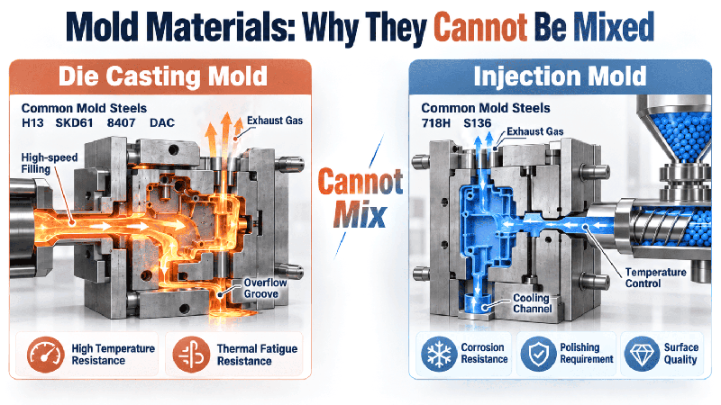
The exact grade still depends on the project. Production volume, cavity geometry, surface requirements, and expected tool life are usually more important than choosing a mold steel by name alone.
In the stage-light Pan Shaft project, die-steel selection was considered alongside thermal cycling, local heat concentration, expected tool life, and downstream machining requirements. The tooling decision was tied to the casting process rather than treated as an isolated material choice.
Gating and Venting
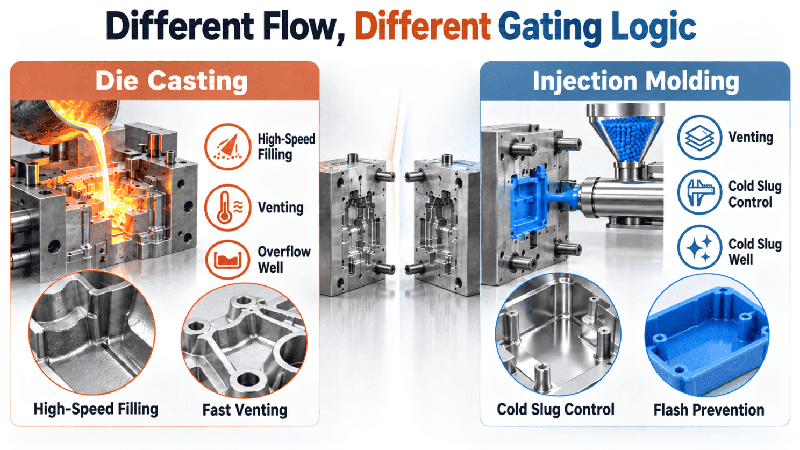
The two processes also handle material flow differently.
In die casting, molten metal must fill the cavity before significant solidification. Gating, overflow, and venting therefore have to accommodate rapid metal flow while managing trapped air and unwanted material.
Injection molding has a different set of concerns. Polymer can cool as it travels through the cavity, and cold material at the start of a shot can affect the filling pattern. Gate location, runner design, cold-slug wells, and venting all influence the final part.
Poor venting can cause problems in both processes, but the defects do not develop in exactly the same way. A plastic injection mold therefore cannot simply be treated as a lower-temperature version of a die-casting die.
Cooling and Thermal Management
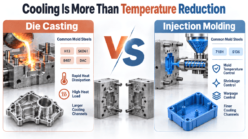
Cooling affects both processes, but the engineering concern is different.
Die casting introduces a large thermal load into the die with every shot. Cooling has to remove heat without creating unstable temperature gradients or excessive thermal cycling. Local hot spots can affect both casting quality and die life.
In injection molding, cooling has a direct relationship with polymer shrinkage and dimensional stability. Uneven cooling can contribute to warpage, sink marks, crystallization differences, and residual stress.
Cooling channels should therefore be considered alongside wall thickness, gate position, material selection, and critical dimensions. Changing one of these variables can change the thermal behavior of the part.
Cavity Surface and Part Release
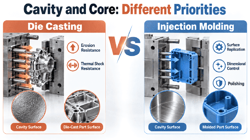
Die-casting cavities have to tolerate repeated metal flow, thermal cycling, and potential erosion. Injection molds place more emphasis on surface replication because polish and texture can transfer directly to the molded part.
That matters on visible plastic housings. A surface that looks acceptable in CAD may require a specific polish or texture in the mold, and ejector locations may become visible on a cosmetic surface.
Die-cast parts have different priorities. A structural casting may accept a relatively simple external finish while requiring a machined bore or mounting face to meet the assembly requirement.
Ejection also has to match the material. Die-cast parts may require substantial release force after solidification. Plastic parts can show ejector marks, scuffing, deformation, or stress whitening if release conditions are poorly matched to the geometry.
Die Casting vs. Injection Molding Cost
There is no fixed cost winner between die casting and injection molding. Tooling is only one part of the calculation; material, cycle time, yield, machining, finishing, inspection, maintenance, and production quantity can all change the economics.
A useful starting point is:
Total manufacturing cost = tooling cost + unit production cost × quantity + secondary processing
For a real quotation, the main cost drivers are usually:
- Tool complexity, steel, and heat treatment
- Cavity count and mold mechanisms
- Material cost, utilization, and cycle time
- Scrap and yield
- CNC machining and finishing
- Inspection and tool maintenance
- Expected production quantity
A die-casting die can require substantial upfront investment because it has to withstand repeated thermal and mechanical loading. Plastic tooling can also become expensive when the part requires multiple cavities, slides, complex ejection, demanding cosmetic surfaces, or other mechanisms.
Tool life is another variable rather than a fixed number. Tool life can vary substantially between the two processes. Injection molds may reach approximately 500,000–1,000,000 cycles in some applications, while die-casting tooling may be closer to 50,000–100,000 cycles. Actual life depends on part size, complexity, tool material, production conditions, and maintenance.
For procurement, the useful comparison is the total manufacturing cost at the planned quantity, not the initial mold price alone.
Production Volume Changes the Economics
Production volume matters because tooling investment has to be spread across the parts produced. It does not, however, make an unsuitable process suitable.
For low-volume work, dedicated production tooling can represent a large share of the total project cost. A prototype or short-run route may make more sense while geometry, fit, and function are still changing.
At higher volumes, cycle time, cavity count, material consumption, process stability, scrap rate, tool maintenance, and secondary operations have a much larger effect on unit cost.
For a new part, the review can follow this order:
- Define what the part must do.
- Select the material family.
- Check the geometry against the process.
- Estimate production quantity.
- Compare tooling and unit cost.
- Include machining, finishing, inspection, and assembly.
- Review the production route before committing to tooling.
A validated prototype does not automatically mean the design is ready for production tooling.
Design Constraints for Die Casting and Injection Molding
The same CAD model can create very different manufacturing problems in metal and plastic. Wall thickness, draft, transitions, shrinkage, tolerances, parting lines, and surface requirements should be checked against the selected process.
| Design factor | Die Casting | Plastic Injection Molding |
|---|---|---|
| Wall thickness | Thin sections can create filling issues; thick areas can increase porosity and uneven solidification | Large thickness changes can increase sink, shrinkage, stress, and warpage |
| Draft | Supports release and protects die surfaces | Supports release and helps prevent scuffing or cosmetic damage |
| Tolerances | Critical mating features may require CNC machining | Depends on resin shrinkage, geometry, tooling, and process control |
| Surface | May require trimming, blasting, machining, or coating | Mold polish and texture can transfer directly to the part |
| Undercuts | May require slides or other die mechanisms | May require slides, lifters, or geometry changes |
| Thick sections | Can increase porosity and solidification problems | Can produce sink marks and uneven cooling |
Wall Thickness and Geometry
Wall thickness should support the way material fills and cools rather than simply follow a convenient CAD shape.
In die casting, a very thin section may not fill reliably, while a heavy section can remain hot longer and develop porosity or uneven solidification. In injection molding, thick areas cool more slowly and can pull against thinner sections as the polymer shrinks.
Ribs and bosses need the same attention. Adding material around a mounting feature may improve local stiffness, but an oversized boss can also create a sink mark or uneven cooling problem in an injection-molded part.
Draft and Parting Lines
Draft helps the part leave the mold without excessive friction. The actual requirement depends on cavity depth, surface finish, texture, material, and tooling conditions.
A general reference of approximately 0.5°–3° is sometimes used as an early design range, but it should not be treated as a universal rule. Deep textured surfaces and cosmetic requirements can require a different approach.
Parting-line location also matters. Moving it can simplify a tool but place a visible witness line across a cosmetic surface or change where draft and ejection need to be applied.
Which Dimensions Actually Need Tight Tolerances?
Tight tolerances should be reserved for features that control the function of the assembly.
Typical examples include:
- Bearing or shaft fits
- Locating bores
- Sealing faces
- Threaded interfaces
- Mounting-hole patterns
- Functional clearances
- Datum relationships
On a die-cast component, it can be more economical to leave machining allowance and finish only these features. That approach was used on Mastars’ Pan Shaft manufacturing project, where cast geometry was followed by machining for threaded, locating, and mounting interfaces.
For injection molding, dimensional variation is closely tied to resin behavior, part geometry, mold temperature, cooling, shrinkage, and process control. A tight drawing tolerance should therefore be discussed with the molding process rather than assumed to be achievable simply because the mold is CNC-machined accurately.
Defects and Secondary Operations
The likely defects are different because the two materials respond differently during filling and cooling. The final manufacturing route should account for those risks as well as the operations required after forming.
Common Die-Casting Risks
Typical issues include:
- Porosity
- Incomplete filling
- Cold shuts
- Flash
- Die wear
- Dimensional variation
- Distortion
- Porosity exposed during machining
That last issue matters when a cast surface later becomes a precision interface.
The Pan Shaft includes a flange, raised bosses, mounting holes, and a rear cylindrical feature. After casting, gates and overflow are removed, while selected areas are machined to create threaded, locating, and mounting interfaces. The dimensional review is tied to final assembly rather than stopping when the casting leaves the die.
Common Injection-Molding Risks
Injection molding has its own failure modes:
- Sink marks
- Warpage
- Uneven shrinkage
- Weld lines
- Flash
- Short shots
- Residual stress
- Ejector marks
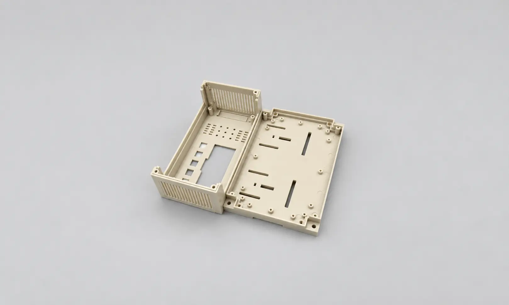
A large flat housing with several ribs, for example, can develop warpage if its sections cool at different rates. The problem may not be obvious from the finished CAD model; it becomes apparent when the molding process creates an uneven thermal history.
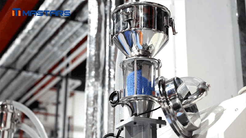
In a rehabilitation-device project using rigid PA12 TR90 and flexible ESTANE TPU, repeated mold trials were used to verify the curved geometry, component positioning, mold actions, and staged overmolding sequence before production.
A successful first sample does not necessarily demonstrate production repeatability, especially when geometry or material interaction is difficult.
Can One Product Use Both Processes?
Yes. A product can combine die-cast and injection-molded components when different sections have different functional requirements.
Examples include:
- Die-cast aluminum structure with an injection-molded outer cover
- Die-cast heat-dissipating body with plastic insulating components
- Metal load-bearing frame with plastic covers
- Die-cast component with CNC-machined interfaces assembled to injection-molded parts
- Metal structure with an overmolded polymer grip or protective section
Using both materials can avoid forcing the entire product into one material. The metal section may handle load or heat while the polymer section provides insulation or a comfortable external surface.
The interface between the two parts then becomes an engineering consideration of its own. Locating features, dimensional stack-up, fasteners, sealing, and assembly sequence all need to work together.
Matching the Process to the Part
The quickest way to narrow the choice is to identify the requirement that is hardest to satisfy with the alternative process.
| If the project priority is… | Start by evaluating… |
|---|---|
| Metal strength or structural stiffness | Die casting |
| Heat dissipation | Die casting |
| Electrical conductivity or EMI shielding | Die casting |
| Low weight | Plastic injection molding |
| Electrical insulation | Plastic injection molding |
| Transparent, colored, or textured surfaces | Plastic injection molding |
| Complex cosmetic plastic housing | Plastic injection molding |
| Metal structure plus plastic protection or insulation | Combined route |
| Critical metal bores, threads, or sealing faces | Die casting + CNC machining |
| Uncertain material or process route | DFM and manufacturing-route review before tooling |
For a new part, the review can follow:
Function → Material → Geometry → Volume → Tooling → Unit Cost → Secondary Operations → Inspection → Production
That sequence helps expose problems before they become tooling changes.
Choosing the Manufacturing Route Before the Tool Is Built
For a new part, the material requirement should be established first. Geometry and production volume then narrow the feasible processes, while tooling, tolerances, machining, finishing, and inspection determine whether the proposed route is practical at production scale.
A die-cast part may need CNC machining at a few critical interfaces, while an injection-molded part may require tighter control of cooling, shrinkage, texture, and ejection. Both routes can produce repeatable production parts, but they get there through different process controls.
The comparison is best made at the part level, rather than by comparing the two technologies in isolation.
Need Help Choosing Between Die Casting and Injection Molding?
A CAD model, material requirement, target quantity, critical dimensions, and functional requirements provide enough information for an initial manufacturing-route review. If the material or process choice is still open, those details can be evaluated before tooling is committed.
Include any critical dimensions, material requirements, surface requirements, target production quantity, or existing prototype information that could affect the manufacturing route.
FAQ
What is the main difference between die casting and plastic injection molding?
Die casting forms molten metal, typically aluminum, zinc, or magnesium alloys, under high pressure in a metal die. Plastic injection molding forms molten polymer in an injection mold. The two processes share basic mold concepts, but their filling, cooling, shrinkage, tooling, and ejection conditions are different.
Is die casting stronger than injection molding?
It depends on the material and the part design. A die-cast metal component can provide structural stiffness, heat dissipation, and electrical conductivity that many plastics cannot match. Engineering polymers can still provide adequate strength for many housings and structural components, while offering lower weight or electrical insulation.
The comparison should be made between specific material grades and actual loading conditions rather than between “metal” and “plastic” in general.
Is injection molding cheaper than die casting?
Not necessarily. Injection molding can provide a lower unit cost when production volume is sufficient to amortize the mold, but resin cost, cycle time, cavity count, scrap, finishing, inspection, and maintenance all affect the result.
Die casting can also be economical for repeated production of metal components, particularly when the casting reduces the amount of material that would otherwise require machining.
When does a die-cast part need CNC machining after casting?
CNC machining is usually considered when a feature has a tighter dimensional or geometric requirement than the casting process can reliably maintain. Common examples are precision bores, threads, locating surfaces, sealing faces, and critical mounting interfaces.
Machining allowance should be considered during part and die design. Mastars can combine CNC machining with die casting when selected features need a tighter finish or dimensional relationship.
Can a product use both die-cast and injection-molded components?
Yes. Combining the two processes can make sense when the product needs both metal and polymer functions. A die-cast component can provide structural support or heat dissipation, while injection-molded components can provide insulation, protection, appearance, or weight reduction.
The connection between the parts needs its own review. Locating features, tolerances, sealing, fasteners, and assembly sequence can all affect whether the combined design works reliably.
Why can’t a plastic injection mold be used for die casting?
The tooling sees very different conditions. Die-casting dies must withstand molten metal, rapid filling, high pressure, thermal cycling, and metal erosion. Plastic injection molds are designed around polymer flow, cooling, shrinkage, surface replication, and controlled release.
As a result, mold steel, gating, venting, cooling, cavity construction, and ejection cannot simply be transferred from one process to the other.
What is the difference between metal injection molding and die casting?
Metal injection molding (MIM) is a separate metal-forming process that uses metal powder and binder, followed by molding, debinding, and sintering. Its material behavior, shrinkage, tooling, and suitable part geometry differ from conventional die casting.
MIM deserves a separate process comparison because its economics and design considerations are different from those of plastic injection molding and die casting.
How should the manufacturing process be selected for a new part?
Start with the part’s functional requirements: strength, stiffness, temperature resistance, conductivity, insulation, weight, appearance, dimensional stability, and service environment. Then compare suitable materials, geometry, production volume, tooling investment, tolerances, secondary machining, finishing, inspection, and assembly.
When the route is still uncertain, a design for manufacturability review before tooling can identify problems while the design is still relatively easy to change.
Hot Articles
Hot Tags
Stay Connected!


Manufacturing on Demand
Please fill in the following information to obtain plan details (information is confidential and not disclosed publicly), we will contact you within 24 hours, please keep your phone available!
Upload a 3D/2D model to see instant pricing, lead time, and DFM feedback.