



Compression Deflection: What It Means, Testing, and Applications


When a gasket, foam pad, seal, or elastomeric support is compressed, engineers need to know more than whether the material is soft or hard. Compression deflection describes the force or compressive stress associated with a specified amount of deformation, helping engineers understand how a material responds under compression.
Common test points include 25% and 50% compression, but the reported value is meaningful only when the test method, specimen geometry, compression level, and conditions are known. For a finished part, geometry and manufacturing variation can also change the actual force response.
This guide explains how to interpret compression deflection data, how major ASTM and ISO standards relate to the measurement, and how to use the data when selecting materials and designing compression-loaded parts.
Compression Deflection: The Basic Measurement
Compression deflection describes the force or compressive stress required to deform a material by a specified amount. It is normally reported at a defined compression level, such as 25% or 50%, and may be expressed as force or stress depending on the test method.
The basic relationship is:
Compressive Stress = Force ÷ Loaded Area
For example, if a specimen requires 100 N over a loaded area of 1,000 mm²:
100 N ÷ 1,000 mm² = 0.1 MPa
A force value in N or lbf tells you the applied load. A stress value in psi, kPa, or MPa accounts for the area over which that load is distributed. This distinction matters when comparing supplier data.
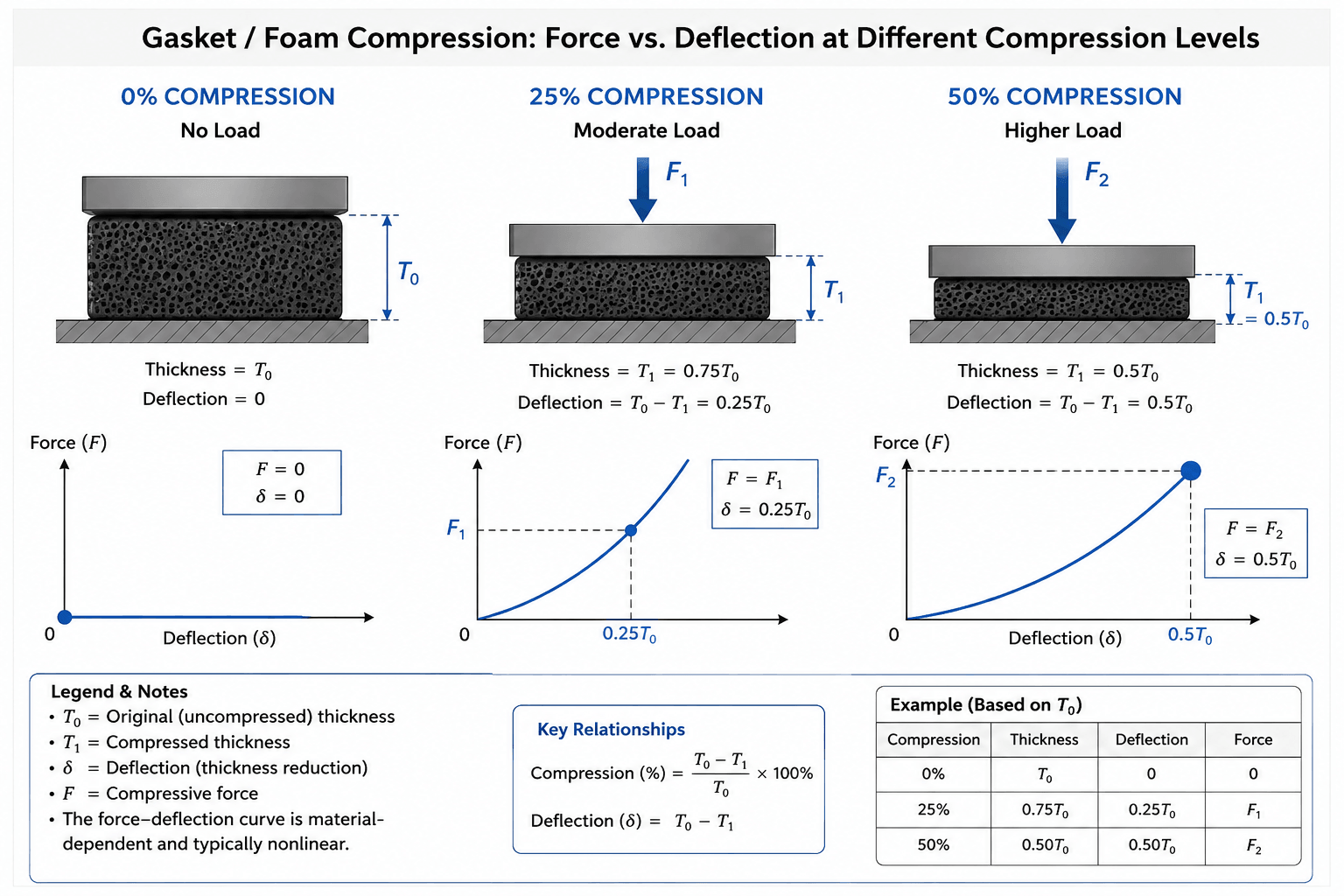
What 25% and 50% Compression Mean?
At 25% compression, a specimen is compressed by one quarter of its original thickness. At 50% compression, its thickness is reduced by half.
| Compression Level | Meaning | Typical Use |
|---|---|---|
| 25% | 25% reduction in original thickness | Moderate compression response |
| 50% | 50% reduction in original thickness | Deeper compression response |
These are different points on the force-deflection curve. The response is not necessarily linear, particularly for cellular materials. If a gasket operates around 20–30% compression, a 50% compression value should not automatically be treated as its design value.
Compression Deflection vs. Compression Set, Durometer, and IFD
Compression deflection measures force or stress during compression, compression set measures permanent deformation after compression and unloading, and durometer measures resistance to indentation. These properties answer different engineering questions and should not be used interchangeably.
| Property | What It Tells You | Typical Reporting |
|---|---|---|
| Compression Deflection | Force/stress at a specified compression | N, lbf, psi, kPa, MPa |
| Compression Set | Permanent deformation after compression | % |
| Durometer | Resistance to indentation | Shore hardness (Shore A, Shore D, etc.) |
A gasket may need enough initial compression force to maintain contact while also retaining recovery after long-term compression. Looking at compression deflection alone does not answer the compression-set question.
Why Durometer Cannot Replace Compression Deflection?
Durometer is useful for comparing hardness, but it does not describe the complete force response of a component under compression. Two materials with similar Shore hardness can behave differently because formulation, thickness, geometry, and loading conditions also affect compression behavior.
CFD, CLD, and IFD: Check the Method
Compression Force Deflection (CFD), Compression Load Deflection (CLD), and Indentation Force Deflection (IFD) appear in different material and test contexts, particularly for flexible foams. They should not be assumed to be interchangeable.
When comparing supplier data, check:
- Material type and grade
- Test standard or method
- Compression or indentation level
- Specimen configuration
- Force or stress units
The test method behind the abbreviation matters more than the abbreviation itself.
How Compression Deflection Testing Works
A compression deflection test measures how a defined specimen responds as it is compressed under controlled conditions. The procedure varies by material and standard, but the basic sequence is specimen preparation, controlled deformation, force measurement, and reporting at a specified compression level.
A typical test involves:
- Preparing the specimen according to the applicable standard.
- Measuring initial thickness and dimensions.
- Applying the specified compression.
- Recording force and displacement.
- Determining the result at the required compression level.
- Reporting the result with the relevant test conditions.
Thickness, loaded area, compression percentage, loading rate, temperature, conditioning, and material variation can all affect the measured response.
For this reason, a value such as 80 kPa compression deflection is difficult to evaluate without knowing the material, test method, compression level, and specimen configuration.
ASTM and ISO Standards for Compression Deflection
The appropriate compression deflection test depends on the material being evaluated. Common references include ASTM D1056 for flexible cellular rubber and sponge rubber, ASTM D3574 for flexible polyurethane foam, ASTM D575 for compression-deflection characteristics of rubber, and ISO 3386-1 for compressive stress-strain properties of flexible cellular polymeric materials.
| Material Type | Relevant Measurement | Common Reference Standard |
|---|---|---|
| Sponge / cellular rubber | Compression deflection | ASTM D1056 |
| Flexible polyurethane foam | Compression / indentation properties | ASTM D3574 |
| Rubber compounds | Compression-deflection characteristics | ASTM D575 |
| Flexible cellular polymeric materials | Compressive stress-strain properties | ISO 3386-1 |
The material classification matters. A compression value generated under one material standard should not automatically be compared with a result generated under another.
For international sourcing, request the standard together with the compression level, specimen configuration, and reporting conditions.
Reading a Compression Deflection Curve
A compression deflection curve shows how force or compressive stress changes as compression increases. Unlike a single test point, the curve shows how the material responds across the range in which the finished component may actually operate.
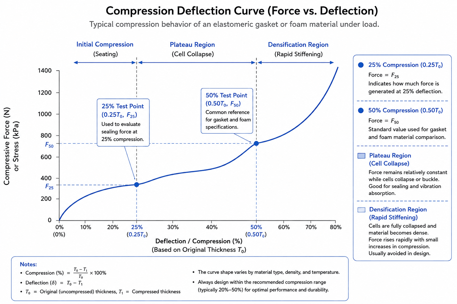
Typical axes are:
- X-axis: Compression or deflection (% or mm)
- Y-axis: Force or compressive stress (N, psi, or MPa)
- 25% / 50% points: Defined compression test levels
- Curve slope: Change in stiffness or resistance
For example, consider a specimen with an initial thickness of 10 mm, 25% compression, a 1,000 mm² loaded area, and a measured force of 120 N.
10 mm × 25% = 2.5 mm deformation
120 N ÷ 1,000 mm² = 0.12 MPa
The loaded area must correspond to the actual test configuration. Comparing force values without considering area can lead to misleading conclusions.
The operating range matters as well. A gasket may work within a relatively narrow compression window because of flange geometry and assembly tolerances, while a cushion may experience a much wider range.
Material, Geometry, Temperature, and Time Can Change the Result
Compression deflection is not a fixed number that can be separated completely from the material and its test conditions. Density, formulation, cell structure, thickness, geometry, temperature, loading rate, and time can all affect the response.
For cellular materials, density and cell structure are important. Open-cell and closed-cell structures can behave differently under compression. For elastomers, polymer chemistry, formulation, and grade also affect stiffness and recovery.
Geometry matters once the material becomes a finished component. A thin gasket, thick foam pad, and solid rubber block can have different force responses even when their nominal material properties appear similar.
For long-term applications, also consider:
- Operating temperature
- Compression duration
- Load cycles
- Fluid or chemical exposure
- Creep and stress relaxation
- Compression set
- Fatigue and recovery
A short-duration room-temperature test should not automatically be treated as a prediction of long-term sealing performance.
Start With the Part When Selecting a Compression Material
The useful compression deflection value is the one that answers a real design requirement. Start with the function of the part, then establish its working compression, load limits, geometry, and service environment.
For a gasket or seal, consider:
- Available compression
- Required contact pressure
- Assembly force
- Dimensional tolerance
- Mating surface geometry
- Long-term compression
For a cushion or support, the priorities may instead include:
- Applied load
- Available deflection
- Support stiffness
- Energy absorption
- Vibration isolation
- Transmitted load
A higher compression deflection value is not automatically better. More stiffness may provide stronger support, but it can also increase assembly force or transmitted load.
The design target is the force-deflection behavior required by the application—not the highest number on a datasheet.
A Gasket Example: Why Material Data Is Only the Starting Point
Gaskets show why material data alone cannot predict finished-part performance. Cross-section, wall thickness, contact geometry, dimensional tolerance, molding conditions, and assembly all affect how the finished component behaves.
Mastars documented this issue in an automotive LSR sealing gasket project. The part included irregular curved surfaces, a thin wall of approximately 0.8–1.2 mm, and a dimensional tolerance requirement of ±0.05 mm. Initial trials encountered bubbles, shrinkage depressions, flash, dimensional instability, and reduced compression resilience after long-term use. The initial qualification rate was only 78%.
The solution involved the material and molding process together rather than changing one material property. The project included material pretreatment and formulation, mold-structure improvements, injection-parameter calibration, post-curing, dimensional inspection, compression set testing, aging tests, and sealing-performance verification.
After optimization, the overall qualification rate reached 98.5%, dimensional tolerance qualification reached 99.2%, and the optimized gasket showed a compression set below 5% after 1,000 hours of high-temperature aging at 120°C.
The manufacturing lesson is straightforward: a compression value measured on a material sample still has to be reproduced in the finished component. Mold design, geometry, process control, and inspection can all affect the result.
From Material Datasheet to Production Part
A material specification describes a controlled test specimen. Production adds variables such as mold design, curing, wall-thickness variation, dimensional tolerance, flash, and process consistency.
For a molded compression-loaded component, design review should cover:
- CAD geometry
- Critical dimensions
- Wall thickness
- Mating surfaces
- Compression interfaces
- Material grade
- Tolerance requirements
- Manufacturing process
This is particularly important for thin-wall silicone parts. Uneven wall thickness can affect molding behavior and dimensional consistency, while parting-line accuracy can affect sealing interfaces.
Mastars' LSR manufacturing capabilities include DFM review, in-process CMM inspection, first article inspection, and process capability reporting, which are relevant when a material property must ultimately be reproduced in a production part.
A Practical Compression Deflection Selection Process
There is no universal compression deflection value for every seal, cushion, or elastomeric component. A practical selection process starts with the function of the part and then narrows the material choice using the conditions that control its performance.
1. Define the Function
Determine whether the component is primarily used for sealing, cushioning, supporting, vibration isolation, or energy absorption.
2. Define the Working Compression
Establish the expected assembly and operating compression. Do not select the material from a generic 25% or 50% value alone.
3. Establish the Load Window
Define both the minimum required contact force and the maximum acceptable assembly or transmitted load.
4. Add the Service Environment
Consider temperature, fluids, chemicals, humidity, aging, and exposure time.
5. Check Recovery
For long-term or cyclic compression, review compression set, stress relaxation, creep, and fatigue as applicable.
6. Validate the Finished Part
For critical applications, representative testing of the production-relevant material and geometry can reveal effects that a standardized flat specimen cannot capture.
When Should You Ask a Supplier for More Test Data?
A generic datasheet may be enough for an early material screen. More application-specific data is warranted when compression performance directly affects product function, particularly for critical sealing interfaces, long-term compression, high temperatures, tight dimensional interfaces, or significant assembly loads.
When comparing suppliers, request the test standard, compression level, specimen configuration, and environmental conditions with the numerical result.
If those details are missing, apparently similar compression deflection values may not be directly comparable.
Compression Deflection FAQs
Is 25% Compression Always the Right Design Point?
No. Twenty-five percent is a useful test point for some materials and applications, but the correct compression range depends on geometry, sealing or support requirements, assembly tolerance, and service conditions.
Can I Compare Compression Deflection Values From Two Suppliers?
Only when the material, test method, compression level, specimen configuration, and reporting units are sufficiently comparable. A higher number does not necessarily indicate better performance.
Should I Test the Material or the Finished Part?
For early material screening, standardized material testing is useful. When geometry, sealing behavior, or long-term compression is critical, testing a representative finished part can reveal effects that a flat specimen cannot capture.
What Information Should I Give a Supplier?
Provide the material requirement, CAD geometry, target compression, expected load, operating temperature, and service conditions if known. For compression-loaded parts, the geometry is often as important as the material specification.
When Compression Deflection Becomes a Manufacturing Question
Compression deflection starts as a material property. In a working gasket, seal, cushion, or elastomeric support, it becomes part of a larger engineering problem involving material, geometry, assembly, and manufacturing consistency.
For compression-loaded components, Mastars can review the material requirement together with CAD geometry, critical interfaces, tolerances, and the manufacturing process.
Need Help with Compression-Loaded Parts?
Share your CAD file, material requirement, target compression, and operating conditions. Rough information is fine to start.
Get a Quote →Hot Articles

Hot Tags
Stay Connected!


Manufacturing on Demand
Please fill in the following information to obtain plan details (information is confidential and not disclosed publicly), we will contact you within 24 hours, please keep your phone available!
Upload a 3D/2D model to see instant pricing, lead time, and DFM feedback.