



Thermoforming vs Vacuum Forming: How the Processes Relate and Differ in Practice


For a large plastic cover or enclosure, vacuum forming is often the first thermoforming method worth evaluating. The terminology causes confusion because thermoforming is the broader manufacturing process, while vacuum forming is one method within it. Pressure forming, plug-assisted forming, and twin-sheet forming are other thermoforming approaches.
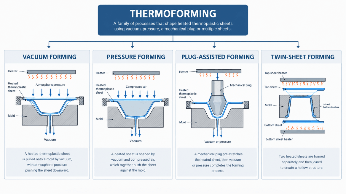
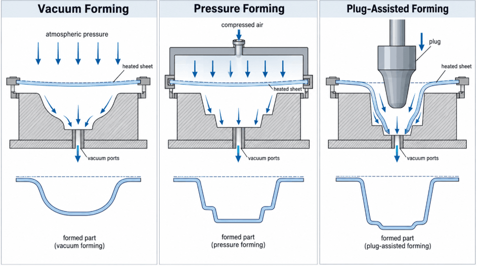
The key difference is how forming force is applied after the sheet reaches its forming temperature. Vacuum removes air between the heated sheet and the mold, allowing atmospheric pressure to force the sheet against the tool. Pressure forming adds compressed air, while plug-assisted forming uses mechanical pre-stretching to move material into deeper areas. Twin-sheet forming uses two sheets to create hollow or double-wall structures.
The choice matters when a part has deep draws, textured surfaces, demanding wall distribution, or tightly controlled assembly features. A large equipment cover may be a straightforward vacuum-forming job. A housing with deep internal geometry or numerous molded-in features may require another thermoforming method or a comparison with injection molding.
The sections below focus on the factors that change that decision: forming method, material behavior, wall distribution, tooling, geometry, production volume, and secondary operations.
Thermoforming Is the Process Family; Vacuum Forming Is One Method
Thermoforming is the process family; vacuum forming is one specific thermoforming method. Thermoforming heats a thermoplastic sheet to a controlled forming temperature, then shapes it over or into a mold using vacuum, air pressure, mechanical assistance, or a combination of these methods. The formed sheet is cooled, released, trimmed, and may receive additional machining or assembly.
What Is the Thermoforming Process?
A typical thermoforming process starts with a flat thermoplastic sheet rather than plastic pellets. The sheet is heated until it reaches a suitable forming window, positioned over or into the tooling, formed by vacuum, pressure, mechanical assistance, or a combination of these forces, then cooled before trimming.
A typical sequence is:
- Heat the thermoplastic sheet.
- Bring the sheet to the required forming temperature.
- Position it over or into the tool.
- Apply vacuum, air pressure, mechanical assistance, or a combination.
- Allow the material to conform to the tool.
- Cool the formed part.
- Release the part from the tool.
- Trim and machine the required features.
- Complete assembly or other secondary operations.
The forming operation establishes the main three-dimensional shape. Connector openings, mounting holes, trim edges, sealing interfaces, and other controlled features may be produced during secondary machining when the forming process cannot hold those features consistently enough.
What Is Vacuum Forming?
Vacuum forming is generally best suited to single-sided shapes with relatively simple geometry. It works well for trays, liners, covers, panels, packaging, and larger housings where the outer contour matters more than complex molded-in features.
The main constraint is material movement. As the sheet travels over the mold, it stretches. Deep draws, tight corners, uneven heating, and long material paths can therefore produce local thinning or inconsistent wall distribution.
Vacuum forming is attractive when:
- The part has a relatively open or single-sided geometry.
- Large surface area matters more than small molded features.
- Smooth curves are acceptable.
- Tooling cost needs to stay controlled.
- The design may still change during development.
- Production volume does not justify a more complex molding route.
A vacuum-formed part should still be reviewed for wall thickness, draft, draw depth, venting, trim allowance, and critical interfaces before tooling is released.
What Other Thermoforming Methods Are Available?
Vacuum forming is only one route. Pressure forming, plug-assisted forming, twin-sheet forming, and matched-tool approaches add different ways to control material movement or increase detail.
| Process | Best suited for | Main limitation |
|---|---|---|
| Vacuum forming | Large shells, covers, panels, trays, liners, relatively simple housings | Detail and wall distribution become harder as geometry becomes deeper |
| Pressure forming | Textured surfaces, defined edges, finer cosmetic detail | More tooling and process development |
| Plug-assisted forming | Deep draws and difficult material distribution | Additional forming step and tooling |
| Twin-sheet forming | Hollow or double-wall components | Two-sheet tooling and joining requirements |
The process should be selected around the geometry the tool must reproduce and the wall distribution that geometry will produce.
How to Choose the Right Thermoforming Method?
Vacuum forming is usually the starting point for simple, single-sided geometry. Pressure or mechanical assistance becomes more useful when the part requires greater detail, deeper geometry, or better control of material distribution.
Vacuum Forming for Large Shells
Large equipment covers, protective housings, panels, trays, liners, and similar parts can be good vacuum-forming candidates because the process can shape a relatively large surface without requiring a complex closed mold.
The trade-off appears when the part becomes feature-heavy. A shell with several large openings can usually be trimmed after forming. A housing that also needs precise bosses, snap fits, ribs, threaded features, and controlled mating surfaces presents a different manufacturing problem. Those features may require secondary machining, hardware, bonding, or a different molding process.
When Is Pressure Forming a Better Choice?
Pressure forming becomes useful when surface detail, texture, edge definition, or cosmetic appearance is more demanding than standard vacuum forming can comfortably reproduce. It combines vacuum with positive air pressure, increasing the force that pushes the heated sheet against the tool.
This can improve reproduction of:
- Fine textures
- Logos and lettering
- Defined edges
- Smaller radii
- More controlled cosmetic surfaces
The additional forming control comes with more tooling and process-development requirements. If the design only needs a smooth outer shell, that extra complexity may provide little benefit.
When Does Plug-Assisted Forming Make Sense?
Plug assistance is useful when a deep draw would otherwise stretch the sheet unevenly before it reaches the final mold surface. A mechanical plug moves material into the cavity before vacuum or pressure completes the forming operation, giving the process more control over where the sheet is distributed.
This matters for parts where a deep cavity has relatively narrow sections or where a simple vacuum pull would leave critical areas too thin.
The plug shape, material temperature, draw depth, timing, and mold geometry still influence final wall distribution, so plug assistance does not remove the need for DFM.
When Is Twin-Sheet Forming Useful?
Twin-sheet forming is suited to components that need two formed skins joined around their perimeter or at selected internal locations. It can produce hollow structures with more depth than a single formed sheet.
It can be useful for certain ducts, structural covers, pallets, and other hollow components where a single shell would require extensive assembly.
The trade-off is tooling and process complexity. The two sheets must be heated and formed consistently, and the joining area becomes part of the structural and dimensional design.
How Do Materials and Wall Thickness Affect Thermoforming?
Material choice affects forming temperature, stretch behavior, surface appearance, stiffness, chemical resistance, and the amount of wall-thickness variation a part can tolerate. A thermoformed part starts with a uniform sheet, but the final wall is rarely uniform because material redistributes as the sheet stretches over the tool.
Common Thermoforming Materials
Common thermoforming materials include ABS, HIPS, PETG, polycarbonate, PMMA, PP, PVC, and other application-specific sheet grades. The choice depends on stiffness, impact resistance, transparency, chemical resistance, appearance, temperature exposure, and regulatory requirements.
| Material | Why it is commonly selected | Engineering consideration |
|---|---|---|
| ABS | Impact resistance, good appearance, broad industrial use | Forming conditions and surface texture affect appearance |
| HIPS | Cost-sensitive housings, trays, packaging | Lower performance than engineering-grade plastics in demanding environments |
| PETG | Clarity, toughness, ease of forming | Surface and temperature requirements should be checked |
| Polycarbonate | High impact resistance and demanding applications | Forming conditions and material handling require tighter control |
| PMMA | Optical clarity and appearance | More sensitive to scratching and impact than polycarbonate |
| PP | Chemical resistance and low density | Forming conditions require attention to material behavior |
| PVC | Chemical resistance and packaging applications | Grade selection must match the application and regulatory requirements |
For production parts, specify the actual sheet grade rather than only the generic polymer family when material behavior affects fit, appearance, or testing.
How Does Wall Thickness Change During Forming?
Starting sheet thickness does not equal final wall thickness throughout a thermoformed part. Deep draws, corners, sidewalls, raised features, and other areas with high material travel can become thinner as the sheet stretches.
A simple geometry with a shallow draw may retain a relatively predictable wall distribution. A deep cavity with a small footprint forces the material to travel farther, increasing stretching and thinning.
For a critical housing, the relevant question is not only what sheet thickness to buy, but where that material will end up after forming. Critical walls, sealing surfaces, mounting interfaces, and load-bearing areas should be identified during DFM.
Tooling and Production Economics
Thermoforming can reduce initial tooling complexity compared with injection molding, but tooling cost is only one part of the manufacturing decision. Material utilization, trimming, secondary machining, inspection, cycle time, and production quantity can change the total cost.
Tooling Strategy
Tooling should reflect the expected development and production path rather than the first prototype alone.
A development tool may make sense while geometry is changing or when the immediate objective is fit and functional validation. A production-oriented tool becomes more important when repeatability, surface quality, cycle stability, and production quantity become the priority.
Before committing to tooling, review:
- Part size and draw depth
- Forming method
- Material and sheet thickness
- Draft and release conditions
- Venting
- Surface texture
- Trim strategy
- Critical dimensions
- Expected production quantity
- Secondary machining requirements
A low-cost tool is not necessarily the lowest-cost route if it creates excessive trimming, machining, scrap, or dimensional variation later.
The Main Thermoforming Cost Drivers
| Cost factor | Why it matters |
|---|---|
| Tooling | Tool material and construction affect initial investment and expected production use |
| Sheet material | Polymer, grade, color, thickness, and sheet size affect material cost |
| Material utilization | Large unused areas increase scrap and cost |
| Sheet thickness | Thicker material increases material cost and may change forming behavior |
| Cycle time | Heating and cooling affect production capacity |
| Trimming | Complex trim profiles add tooling or machining time |
| CNC machining | Critical holes, slots, and interfaces may require secondary operations |
| Inspection | Tight dimensional requirements increase inspection effort |
| Assembly | Hardware, bonding, welding, or heat staking add process steps |
Production volume changes the balance between these factors. A low-volume project may favor flexible tooling and secondary operations. As quantity increases, cycle time, repeatability, scrap rate, and tooling life become more important.
Does Higher Production Volume Always Favor Injection Molding?
A higher production volume does not automatically make injection molding the better choice. A large, thin-wall enclosure with relatively simple geometry can remain a thermoforming candidate at higher quantities, while a smaller feature-rich housing may justify injection molding at a lower volume.
Evaluate the part against:
- Overall size
- Wall geometry
- Required detail
- Material
- Critical tolerances
- Production quantity
- Tooling budget
- Secondary operations
- Required repeatability
What Design Rules Matter Before Thermoforming?
Thermoforming DFM should address draft, draw depth, corner radius, wall-thickness distribution, venting, undercuts, and trimming before tooling starts. These features determine how far the sheet must stretch, whether it can release from the tool, and where dimensional variation is likely to appear.
Draft and Demolding
Provide adequate draft to support release from the mold and reduce scuffing or part distortion. The required draft is affected by material, texture, draw depth, tool surface, and forming method.
Textured surfaces generally require more attention because the formed plastic can mechanically lock against the tool surface. A geometry that releases easily with a smooth tool may become difficult to demold after texture is added.
Draw Depth and Material Stretching
Greater draw depth and a smaller forming footprint increase material travel and the risk of thinning, webbing, tearing, or non-uniform walls.
Deep sections should be reviewed together with:
- Starting sheet thickness
- Corner radius
- Draft
- Heating uniformity
- Forming method
- Required final wall thickness
If a critical feature sits at the end of a deep draw, do not assume the nominal sheet thickness represents the material available at that location.
Corners and Radii
Avoid unnecessarily sharp corners. Tight radii force the sheet to stretch locally and can create thin areas, particularly in deep-draw regions.
Larger radii generally give the material more room to move around the geometry. They can also reduce stress concentration and improve tool release.
For cosmetic parts, radius selection also affects how smoothly the material transitions across the surface and how consistently the tool texture is reproduced.
Undercuts
Vacuum forming has limited undercut capability because the formed part must normally release from the tool. Deep or mechanically locked undercuts may require split tooling, mechanical assistance, a different forming approach, or secondary assembly.
A small retention feature that looks insignificant in CAD can therefore determine the tooling concept.
Trimming, Venting, and Secondary Machining
Trimming is normally a separate manufacturing step, so trim allowance and critical feature locations should be considered before forming. Critical holes, sealing edges, and mating boundaries should not be placed directly in areas where the trim condition is difficult to control.
Proper mold venting is also important. Trapped air can prevent the heated sheet from fully conforming to the mold surface, creating incomplete detail or local dimensional problems.
Secondary operations may include:
- CNC trimming
- Drilling
- Slot cutting
- Hardware insertion
- Bonding
- Welding
- Heat staking
- Printing
- Painting
- Assembly
- Inspection
Reserve CNC operations for features that genuinely need tighter control rather than trying to force every dimension into the forming operation.
Thermoforming vs Injection Molding
Thermoforming is often stronger for large, thin-wall, lower-volume, or evolving designs, while injection molding becomes more attractive when a part needs many integrated features, high repeatability, and larger production quantities. The comparison should include tooling and secondary operations, not just the forming step.
| Part requirement | Thermoforming | Injection molding |
|---|---|---|
| Large thin-wall enclosure | Strong candidate | Possible, with more substantial tooling |
| Simple shell geometry | Strong candidate | Possible |
| Integrated ribs and bosses | Often requires secondary work or design compromise | Well suited |
| Snap fits and clips | Limited | Well suited |
| Large openings | Straightforward to trim | Depends on mold and part design |
| Tight interfaces | Often machined after forming | Can often be molded directly |
| Initial tooling investment | Generally lower | Generally higher |
| Design changes during development | Usually easier to accommodate | More expensive after tooling |
| High production repeatability | Requires controlled forming and inspection | Strong fit |
A large shell may be easy to thermoform, while a housing with multiple internal bosses, connector interfaces, snap features, and controlled assembly datums can become expensive to finish through secondary operations.
The same consideration applies when a housing has to accommodate connectors, a PCB, and fastening features. In one Mastars USB charger enclosure project, multiple USB-C openings and internal assembly requirements made those interfaces more important to the manufacturing decision than the outer shell alone.
For parts with extensive molded-in features, injection molding deserves comparison before a thermoforming tool is finalized.
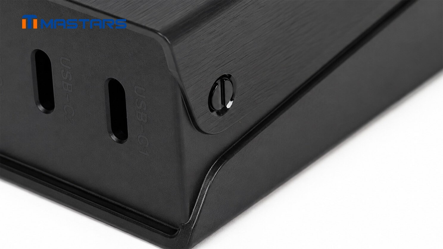
Interface details and enclosure fit are reviewed before production.
What Changes When You Move From Prototype to Production?
A thermoformed prototype can validate fit, appearance, and basic assembly without proving that the production process is stable. Before production, review the final material, wall distribution, tooling, trim strategy, critical dimensions, inspection requirements, and expected quantity.
| Prototype focus | Production focus |
|---|---|
| Fit and assembly | Repeatability |
| Form and appearance | Consistent surface quality |
| Basic function | Process stability |
| Material behavior | Production material and sheet control |
| Design iteration | Final tooling |
| Visual inspection | Defined inspection method |
| One-off dimensional checks | Critical-dimension control |
| Rapid changes | Controlled production process |
A validated prototype does not automatically mean the design is ready for production.
Critical Dimensions
Identify the dimensions that actually control assembly or function. These may include:
- Mounting-hole locations
- Connector openings
- Sealing edges
- Mating surfaces
- Overall envelope
- Wall locations
- Trim boundaries
- Datum relationships
Do not assign unnecessarily tight tolerances to every formed dimension. Thermoforming involves material redistribution, thermal variation, tool condition, cooling, and trimming, so the achievable tolerance should be tied to the manufacturing route and the function of the feature.
Secondary Machining
When a formed part has critical holes, slots, or mating interfaces, secondary machining can separate the forming requirement from the final dimensional requirement.
This can be useful when the outer shell is economical to form but the assembly interface needs tighter control. Include appropriate machining allowance, tool access, datums, and trim strategy in the design from the beginning.
Mastars supports CMM dimensional inspection as well as FAI, IPQC, and FQC processes, which can be relevant when a project moves from prototype dimensions to defined production inspection requirements.
A Short Process Selection Checklist
Start with the part, not the process name:
- Geometry: Is it a large single-sided shell, or does it contain deep draws and complex features?
- Material: Does the required sheet grade have the stiffness, impact, temperature, chemical, or appearance properties the application needs?
- Wall distribution: Where will stretching create potential thin areas?
- Detail: Are texture, lettering, small radii, or defined edges important?
- Tooling: Is the design stable enough for production tooling?
- Secondary operations: Which holes, trim edges, and mating features need machining?
- Production: What quantity and repeatability are required?
If the geometry is simple and large, vacuum forming is often a sensible starting point. If detail or material distribution becomes the limiting factor, evaluate pressure or mechanical assistance. If integrated features dominate the part, compare the complete thermoforming route with injection molding.
Conclusion
Thermoforming and vacuum forming are not two separate competing processes. Vacuum forming is one type of thermoforming, while pressure forming, plug-assisted forming, twin-sheet forming, and other approaches address different geometry and performance requirements.
For a simple large shell, vacuum forming may provide the right balance of tooling cost, flexibility, and production efficiency. When the part requires deeper draws, finer detail, or better control of material distribution, another thermoforming method may be more appropriate. When ribs, bosses, clips, or precision interfaces dominate the design, injection molding deserves comparison.
The useful question is whether the selected process can produce the required geometry, wall distribution, material behavior, tolerances, surface quality, and repeatability at an acceptable total cost.
Send the CAD file, target quantity, material or sheet-thickness requirement, and any critical dimensions or surface requirements that could affect the build.
Rough information is fine to start.
FAQ
Is vacuum forming the same as thermoforming?
No. Vacuum forming is a type of thermoforming. Thermoforming is the broader process family for shaping heated thermoplastic sheet, while vacuum forming uses vacuum to draw the sheet against the mold.
Is vacuum forming cheaper than pressure forming?
Often, for relatively simple geometry. Pressure forming adds compressed air and more tooling or process-development requirements, so the additional cost needs to be justified by the part’s detail or appearance requirements.
Does thermoforming produce uniform wall thickness?
No. The starting sheet may have uniform thickness, but the material stretches during forming. Deep draws, corners, sidewalls, and raised features can become thinner, so wall-thickness distribution should be reviewed during DFM.
What information should I provide for a thermoforming quote?
Provide the CAD file if available, target quantity, material or sheet thickness, critical dimensions, surface requirements, and any assembly or functional requirements. If the design is still being developed, rough information is enough to start.
Hot Articles
Hot Tags
Stay Connected!


Manufacturing on Demand
Please fill in the following information to obtain plan details (information is confidential and not disclosed publicly), we will contact you within 24 hours, please keep your phone available!
Upload a 3D/2D model to see instant pricing, lead time, and DFM feedback.