



Sheet Metal Fabrication vs Stamping: When Should You Switch?


A sheet metal prototype can fit perfectly, pass assembly checks, and still leave one expensive question unresolved: is it worth building a stamping die for production?
The answer rarely comes down to volume alone. Sheet metal fabrication usually makes more sense when the design is still changing, quantities are limited, larger panels or welded assemblies are involved, or fast iteration matters. Stamping becomes more attractive once the geometry is stable, the same part will run repeatedly, and the tooling investment can be spread across enough production volume.
Geometry, material and thickness, critical tolerances, secondary operations, lead time, and expected design changes all affect that decision.
How Do Sheet Metal Fabrication and Stamping Differ?
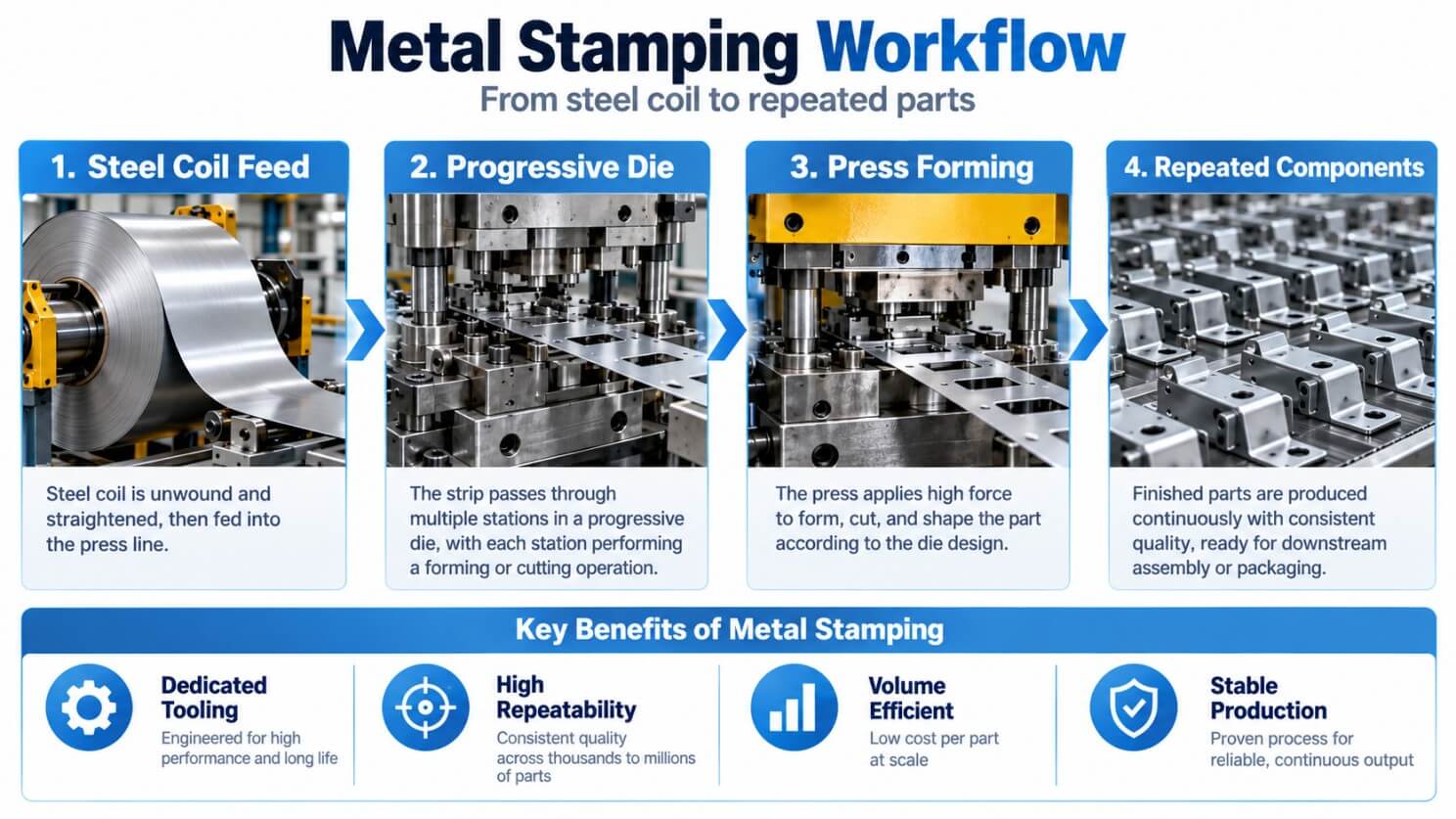
Sheet metal fabrication and metal stamping can produce many of the same basic features, but they approach production differently. Fabrication typically combines laser cutting or CNC punching with press brake bending, fastening or welding, finishing, and assembly. Stamping uses dedicated dies and presses to cut, bend, form, or draw sheet metal through a defined production sequence.
| Factor | Sheet Metal Fabrication | Metal Stamping |
|---|---|---|
| Tooling | Low or no dedicated tooling | Dedicated dies required |
| Best fit | Prototypes, low volume, changing designs, larger parts | Stable designs, repeat production, higher volumes |
| Design changes | Relatively easy to accommodate | May require die modification or new tooling |
| Geometry | Large panels, brackets, chassis, cabinets, welded assemblies | Repeated parts with holes, flanges, tabs, embosses, and formed features |
| Production speed | Flexible, but more operations per part | Fast once tooling and process are established |
| Unit cost | Usually higher at higher volumes | Can become lower at sufficient volume |
| Repeatability | Depends on process sequence and process control | Strong repeatability once the die and process are validated |
Fabrication keeps the manufacturing route flexible because cutting and forming operations can be adjusted without redesigning a dedicated die. Stamping trades that flexibility for a defined process built around repeatable forming conditions.
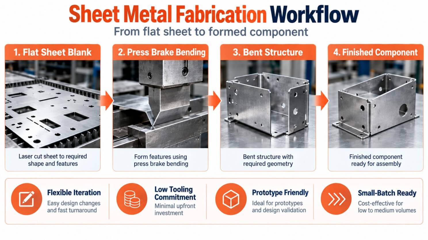
CNC punching and stamping should also not be treated as interchangeable terms. CNC punching uses programmed tooling to create features in sheet material, while stamping uses a dedicated die and press for a planned cutting or forming sequence. Both can be effective, but their tooling requirements and production economics are different.
When Does Stamping Become More Cost-Effective?
Stamping can become more economical when enough parts are produced to recover the initial tooling investment through a lower unit cost. A simple break-even estimate is:
Break-even quantity = Tooling cost ÷ (Fabrication unit cost − Stamping unit cost)
For example, if stamping tooling costs $20,000, fabrication costs $4 per part, and stamping costs $1.50 per part:
$20,000 ÷ ($4.00 − $1.50) = 8,000 parts
At roughly 8,000 parts, the tooling investment reaches its simple unit-cost break-even point.
In practice, maintenance, scrap, secondary operations, inspection, setup, inventory, and engineering changes can all shift the result.
Design stability can change the economics quickly. If a part is expected to change after a few thousand units, the projected stamping savings may never be realized because the die becomes part of the engineering change cost. A small change to a hole pattern or flange can be inexpensive during fabrication but much more consequential once dedicated tooling is involved.
A more useful figure is the number of parts expected before the next major design revision, rather than annual demand alone.
How Does the Engineering Review Change Between Fabrication and Stamping?
The same drawing can raise different manufacturing concerns depending on the process. Fabrication puts more emphasis on bend geometry, forming sequence, hole-to-bend relationships, springback, and accumulated variation between operations. Stamping adds die structure, station planning, material flow, clearances, feed direction, burr orientation, and repeatability at production speed.
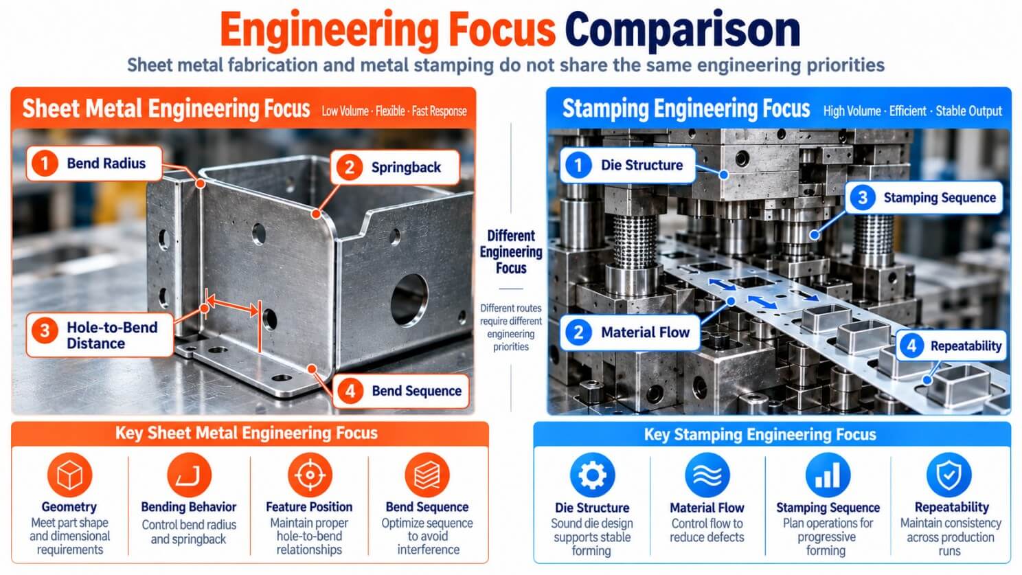
For a fabricated part, a seemingly simple CAD change can have practical consequences. A hole moved 2 mm, a flange shortened by 1 mm, or a mounting interface repositioned after assembly testing may be a routine revision when the part is being laser cut and press-brake formed. The review still needs to check bend access, hole-to-bend distance, springback, and the final relationship between the individual formed features.
For stamped parts, engineers also need to evaluate:
- Die structure and station planning
- Blanking and punching clearance
- Material flow during forming or drawing
- Feed direction and process sequence
- Springback and dimensional recovery
- Burr direction and downstream assembly requirements
- Repeatability over repeated production cycles
Material behavior matters in both routes. Aluminum, stainless steel, carbon steel, and copper can respond differently to bending and forming because strength, ductility, thickness, and springback vary by material and grade.
Tolerances need to be tied to the actual feature and its function. Stamping is not automatically more precise than fabrication. A tight tolerance on a mounting interface, connector opening, or mating feature can require additional process control and inspection regardless of the manufacturing route.
The Mastars professional digital mixer chassis is a useful example. The 18-gauge cold-rolled Zintec steel chassis had a hole-center tolerance of ±0.10 mm, hole-size tolerance of ±0.05 mm, and angular tolerance of ±0.50°. Those requirements were tied to the chassis interfaces and formed enclosure geometry. A hole can meet its own dimensional requirement while still causing an assembly problem if the bend shifts the interface face.
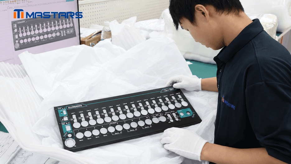
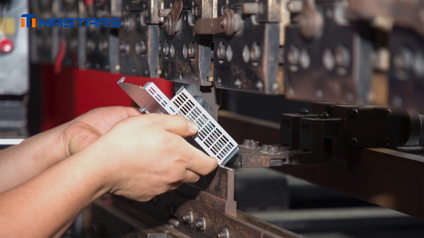
A Mastars engineer checks the enclosure prototype against the CAD model, reviewing its structure, openings, bends, and printed layout.
On this chassis, painting and printing followed the forming operations, so the finished openings and formed surfaces also affected subsequent finishing and graphics registration.
Lead Time and Engineering Changes
Sheet metal fabrication generally provides a shorter path from CAD revision to physical part because it can use standard cutting and forming equipment without dedicated production tooling. That makes it useful while mounting locations, clearances, bend geometry, or assembly relationships are still being validated.
Stamping adds die development, tryout, and process validation before production is ready. Once the tooling is established, the process can deliver high repeatability and fast cycle times. The trade-off appears when the drawing changes.
Consider a bracket whose mounting hole moves after an assembly test. In fabrication, the revised CAD file can normally be cut and formed as a new iteration. In stamping, the same revision may affect the die and require engineering review, modification, and another tryout.
Early builds may involve changes to:
- Mounting locations
- Hole patterns
- Clearances
- Bend dimensions
- Interfaces with mating parts
- Cosmetic features
Fabrication gives the engineering team room to make these changes without committing the project to a fixed tooling strategy too early. Once the design has stabilized and the priority shifts toward repeatability, production rate, and unit cost, dedicated tooling becomes easier to justify.
Can a Fabricated Prototype Transition to Stamping?
Yes. A fabricated prototype can provide valuable physical validation before dedicated stamping tooling is justified, but passing prototype fit and assembly checks does not by itself make the design ready for a stamping die. The production route still needs its own DFM and tooling-feasibility review.
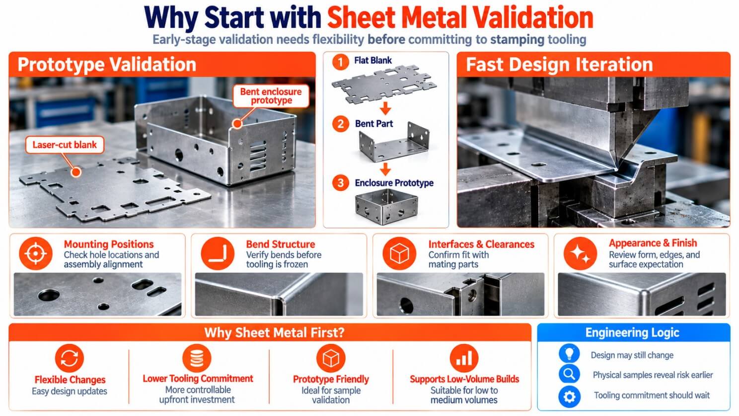
A practical transition can look like this:
1. CAD and drawing review
Identify critical dimensions, interfaces, material requirements, bend features, and assembly constraints.
2. Fabricated prototype
Validate fit, form, mounting locations, clearances, basic assembly, and other design assumptions using a flexible manufacturing route.
3. DFM and tooling review
Check whether holes, flanges, formed features, and bend relationships can be produced without unnecessary tooling complexity. Review material behavior, tolerances, and features that may affect the die.
4. Production economics review
Compare expected volume, tooling investment, unit cost, product lifecycle, and the likelihood of future design changes.
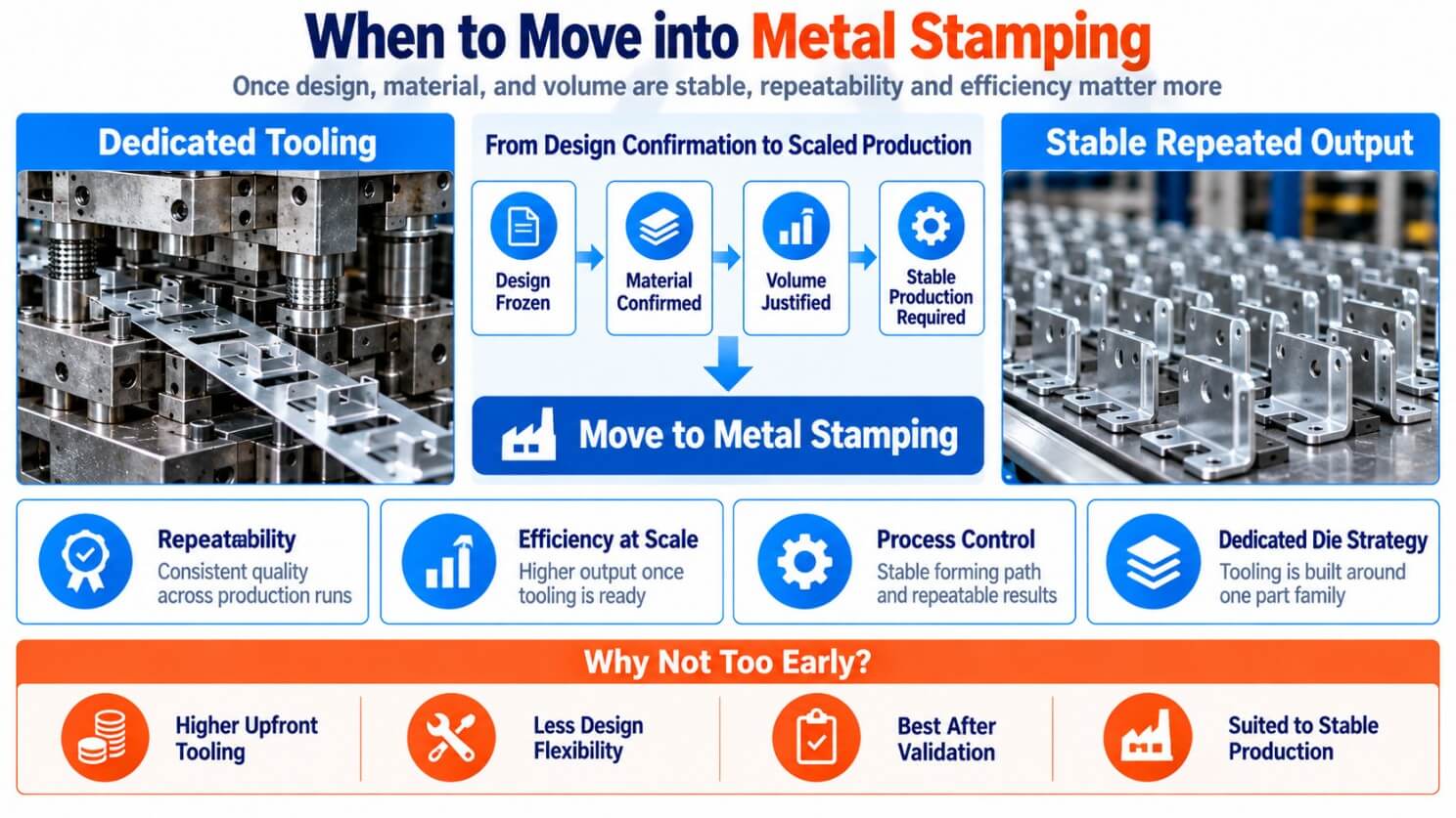
when to move into metal Stamping
5. Stamping feasibility and pilot production
Develop the tooling and forming strategy, validate the process, inspect critical dimensions, and confirm that the production route meets the design requirements.
Prototype approval covers fit, form, assembly, and physical interfaces. Tooling approval also requires evidence that those features can be formed consistently through the intended production sequence.
A successful sample can prove that the current design works. It does not remove the need to check material flow, forming sequence, springback, clearances, and production repeatability before committing to a die.
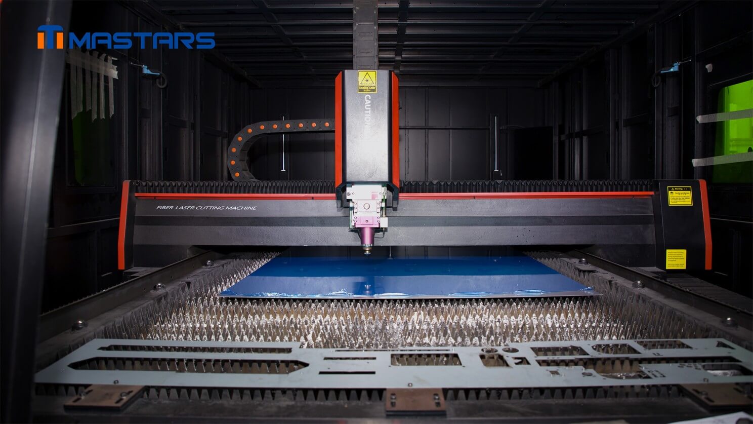
Mastars’ sheet metal fabrication service supports one-off parts, prototypes, assemblies, and short-run production, making fabrication suitable when physical validation and design changes are still part of the development cycle.
How Process Selection Affects Tooling Cost and Production Risk
Selecting the process at the right stage can prevent premature tooling investment and expose manufacturing risks before they become production problems. It also gives engineering and sourcing teams a more realistic basis for planning cost, timing, inspection, and future production changes.
| Project factor | What the process decision affects |
|---|---|
| Tooling investment | Whether dedicated tooling is justified at the current design stage |
| Manufacturing risk | When geometry, material, tolerance, and forming issues are identified |
| Engineering continuity | How prototype findings carry into production planning |
| Production planning | Whether volume, cost, inspection, and lead-time assumptions match the actual route |
If major design questions are still open, fabrication can keep those changes inexpensive. If the geometry is already stable and the same part will run repeatedly, staying with a flexible process indefinitely can leave production savings unrealized.
The timing of the tooling decision can therefore matter as much as the tooling price itself.
What Mistakes Should Be Avoided When Choosing Between Fabrication and Stamping?
Most process-selection mistakes come from evaluating one variable without looking at the rest of the manufacturing sequence. Volume matters, but so do design stability, geometry, tooling risk, secondary operations, and the cost of changing the process later.
Building tooling before the design is stable
If mounting interfaces, hole locations, bend geometry, or other critical features are still changing, dedicated tooling can turn normal engineering revisions into expensive tooling changes.
Choosing fabrication indefinitely for high-repeat production
Fabrication provides flexibility, but a stable part produced repeatedly may eventually justify stamping. Compare the total production cost rather than only the initial tooling investment.
Comparing only die cost with fabrication unit cost
Tooling is only one part of the calculation. Maintenance, scrap, secondary operations, inspection, setup, inventory, and engineering changes can materially affect the result.
Treating CNC punching and stamping as the same process
Both can create holes and profiles in sheet metal, but they use different tooling strategies and offer different levels of flexibility and production economics.
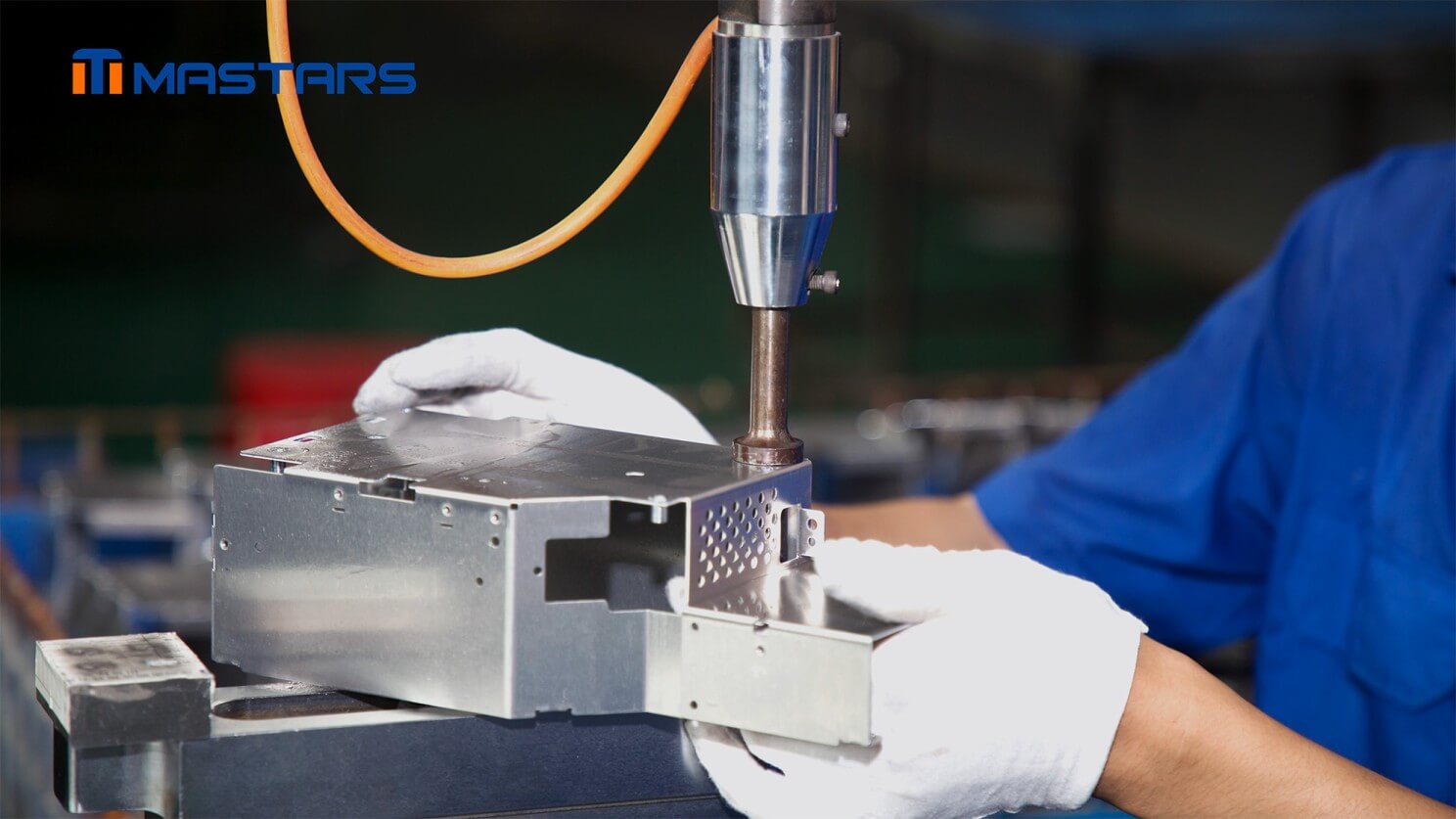
Sheet Metal Fabrication vs Stamping: Which Route Fits Your Part?
Sheet metal fabrication is generally the better choice when the design is still evolving, quantities are limited, large or welded assemblies are involved, or fast physical validation matters. Stamping becomes more attractive when the geometry is stable, the same part will run repeatedly, and the tooling investment is justified by the production volume and product lifecycle.
The manufacturing route can change during the life of the product. Fabrication may be the right answer for early builds and engineering samples, while stamping can become the better production route once the geometry, demand, and process requirements are sufficiently stable.
If a project is moving from prototype validation toward repeat production, reviewing the geometry, material, tolerances, expected volume, and tooling implications together can prevent costly changes later.
Share your CAD files, drawings, expected quantity, material requirements, and any critical dimensions or surface requirements that could affect the build. Rough information is fine to start.
FAQ
Is sheet metal fabrication cheaper than stamping?
It depends on the part and production plan. Fabrication usually has lower upfront tooling costs and is often economical for prototypes, low volumes, and changing designs. Stamping can reduce the unit cost once enough stable production volume exists to recover the tooling investment.
What production volume requires metal stamping?
There is no fixed cutoff. Start with the tooling quote, fabrication cost, stamping unit cost, and the number of parts expected before the next major design revision. That gives a more useful break-even calculation than annual demand alone.
Is stamping more precise than sheet metal fabrication?
Not automatically. Both processes can meet demanding dimensional requirements when the design and process are properly controlled. The achievable result depends on the material, thickness, feature geometry, forming sequence, tooling, process stability, and inspection method.
Can I use sheet metal fabrication for a prototype and stamping for production?
Yes. Fabrication is well suited to physical validation while the design is still changing. Before moving to stamping, review the part for forming sequence, material behavior, tooling requirements, critical tolerances, and production repeatability.
What information should I provide when asking for a fabrication or stamping quote?
CAD files and drawings are the best starting point. Include the material and thickness, expected quantity, critical dimensions or GD&T, surface requirements, assembly requirements, and any known production constraints. If some information is not finalized, rough requirements are still useful for an initial process review.
Hot Articles
Hot Tags
Stay Connected!


Manufacturing on Demand
Please fill in the following information to obtain plan details (information is confidential and not disclosed publicly), we will contact you within 24 hours, please keep your phone available!
Upload a 3D/2D model to see instant pricing, lead time, and DFM feedback.