



How Pre-Deformation Design Controlled Warpage in an Automotive Long Rail Housing


A 1.17 mm Warpage Risk Identified Before Tooling
For an automotive rail housing nearly 500 mm long, even slight warpage can affect how well the long guide channel works.
The part is made from PA6+60%GF. The high glass-fiber content provides greater strength and stiffness, but it also makes deformation harder to control. As the melt fills the cavity, the fibers align with the flow. This creates different shrinkage rates in different directions, which can cause the part to bend or warp.
Before tooling began, mold-flow analysis predicted approximately 1.17 mm of maximum overall warpage, excluding global shrinkage, and about 1.14 mm of maximum displacement in the X direction.
For a part that needs to slide smoothly along a rail, this issue could not wait until the first mold trial. Mastars’ team needed to address it during the mold design stage.
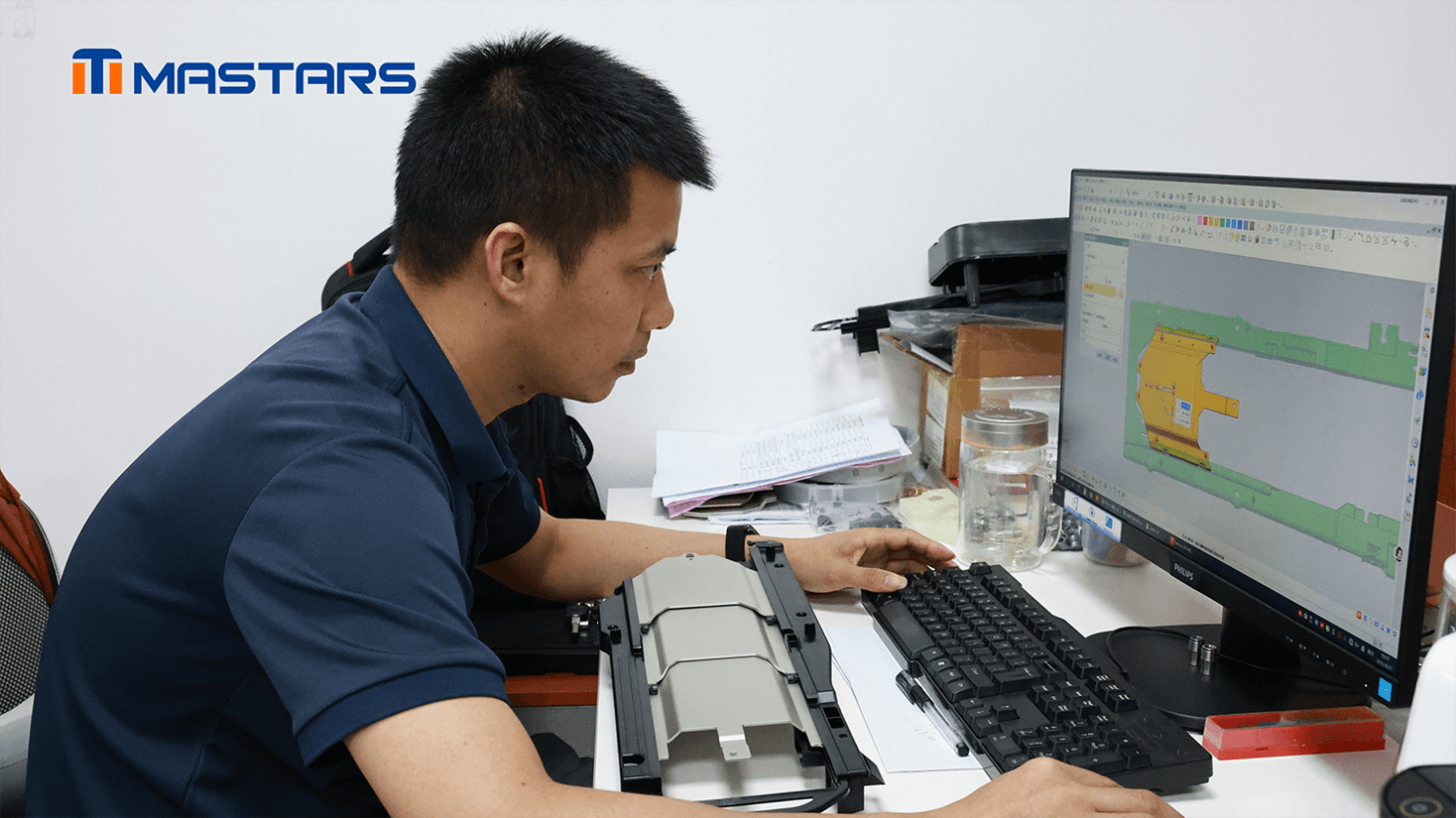
Why Straightness Matters in a Sliding Structure
Glass fibers tend to align with the direction of melt flow during injection molding. Because shrinkage differs parallel and perpendicular to the fiber orientation, a long PA6+60GF part may bend or twist even when its nominal dimensions appear reasonable.
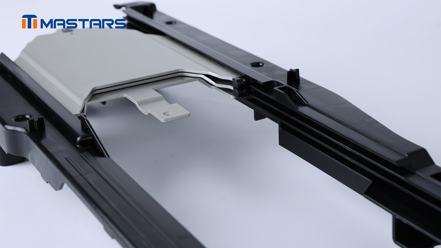
For this housing, the long channel is a functional interface. Excessive warpage could affect its straightness and lead to:
- Increased sliding resistance;
- Local interference during assembly;
- Unstable movement through the rail;
- Mold rework or rejected parts.
The engineering objective was therefore clear: control directional deformation while preserving the strength provided by the high glass-fiber content.
Reviewing the Deformation Before Cutting Steel
The Mastars engineering team identified the material and geometry combination as a warpage risk at the beginning of the project.
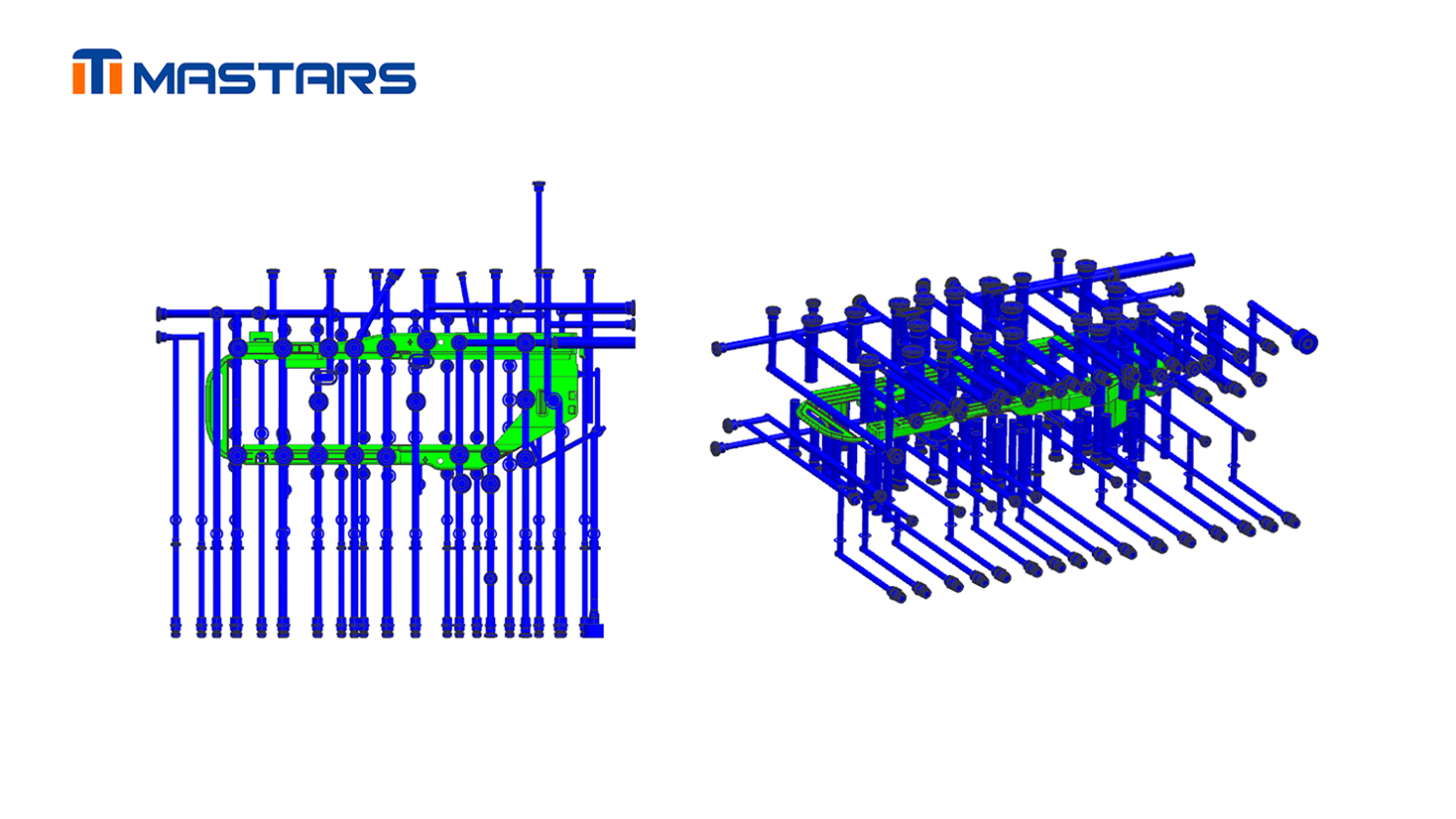
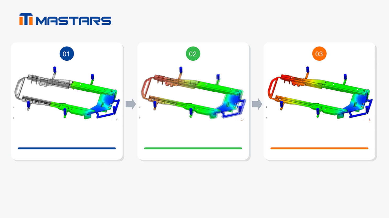
The review focused on four connected factors:
1. Warpage direction and magnitude: Mold-flow analysis was used to predict how the housing would deform after molding and to locate the areas contributing most strongly to the overall distortion.
2. Temperature distribution and cooling balance: Thermal hotspots were examined individually because uneven cooling can create different shrinkage rates along a long component.
3. Melt flow and fiber orientation: Gate positions and filling direction were evaluated to keep the glass-fiber orientation as stable as possible through the long rail structure.
4. Functional straightness after compensation. The predicted deformation was translated into reverse geometry, and the compensated design was simulated again before tooling proceeded.
This allowed the team to treat warpage as a design input instead of waiting for it to appear as a trial-molding defect.
What the Simulation and Assembly Revealed
The initial simulation provided the numerical basis for compensation:
Approximately 1.17 mm maximum overall warpage after removing the effect of global shrinkage;
Approximately 1.14 mm maximum displacement in the X direction, indicating the dominant deformation tendency;
0.15–0.20 mm of safety steel allowance is retained around the rail ribs for controlled adjustment during mold validation.
After trial molding and assembly verification, the long channel showed no obvious bending that affected use. The molded housing could slide through the rail without noticeable jamming caused by channel deformation, meeting the project’s assembly and functional requirements.
Mastars’ Warpage-Control Route
Mastars converted the mold-flow findings into four coordinated mold and process controls.
This created a closed engineering loop:
Predict the deformation → apply reverse compensation → analyze the compensated model → confirm the remaining risk → proceed with moldmaking
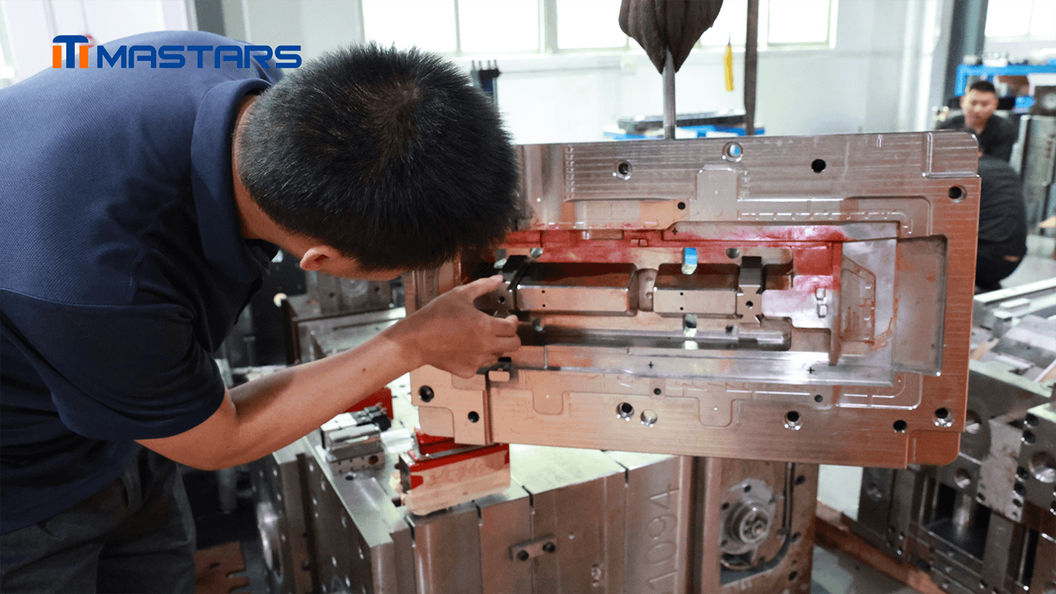
First, reverse compensation was introduced into the cavity geometry against the predicted warpage direction. The compensated geometry was then re-evaluated through mold-flow analysis to confirm that the revised deformation trend aligned with the project requirements.
Second, sufficient cooling circuits were arranged around the long channel and other critical molding areas. Additional attention was given to the identified thermal hotspots to reduce temperature differences and uneven shrinkage across the part.
Third, the gate layout and filling approach were selected to guide the melt along a more controlled path. This helped stabilize fiber orientation and reduce shrinkage differences produced by conflicting flow directions.
Finally, sequential valve-gate timing was used to coordinate the filling process. By opening the gates in a controlled sequence, the melt could advance more continuously and avoid poorly positioned flow fronts meeting around the middle of the housing—a condition that could contribute to local lifting and loss of straightness.
What This Means for Automotive Product Teams
The project demonstrates why deformation control for a long, glass-fiber-reinforced component should begin before the mold is manufactured.
For automotive engineering and project teams, the practical value included:
The 1.17 mm predicted warpage was identified early enough to guide cavity compensation rather than becoming an unexpected trial-molding issue.
The dominant 1.14 mm X-direction displacement provided a defined direction for engineering correction.
The retained 0.15–0.20 mm safety steel allowance preserved adjustment flexibility during mold validation.
Cooling, filling, and compensation were developed as one coordinated strategy rather than isolated corrections.
Assembly verification confirmed that the channel could support smooth sliding without noticeable deformation-related jamming.
Maintaining Control Beyond the First Validation
During subsequent production, the practical next step is to continue monitoring channel straightness and sliding performance under stable material-drying, mold-temperature, injection, and cooling conditions. For PA6+60GF parts, process stability remains essential because changes in moisture, temperature, or filling behavior may affect shrinkage and fiber orientation.
Is Warpage Being Addressed Early Enough in Your Project?
If your automotive component combines a long geometry, a sliding or assembly interface, and high glass-fiber content, reviewing deformation only after the first tool trial may be too late.
What straightness, fit, or sliding requirement must your part maintain after molding? Send your drawings and material requirements to Mastars for an engineering and mold-manufacturing review.

Mastars, the most trusted one-stop manufacturing services provider for low-volume production worldwide!
Hot Articles


Hot Tags
Stay Connected!


Manufacturing on Demand
Please fill in the following information to obtain plan details (information is confidential and not disclosed publicly), we will contact you within 24 hours, please keep your phone available!
Upload a 3D/2D model to see instant pricing, lead time, and DFM feedback.