



Aluminum Alloy Die Casting Defects: From Surface Symptoms to Stable Production


A minor flow mark may be only a cosmetic issue, but it may also indicate that the molten-metal filling process is not fully stable.
A pore that becomes visible only after machining may affect sealing performance, mechanical properties, and downstream machining yield.
High-pressure die casting can produce complex aluminum components quickly, with good surface quality and consistent dimensions. It is therefore commonly used for medium- and high-volume production. However, casting quality is never determined by one machine setting alone.
Part geometry, die design, gating, venting, die thermal balance, shot profile, alloy condition, and ejection method all influence the final result. Die-casting defects are usually created by the interaction of material, geometry, tooling, and process conditions rather than by one isolated parameter. (MDPI)
Effective defect analysis should therefore go beyond adjusting a parameter whenever a visible defect appears.
The location, morphology, distribution, and recurrence pattern of the defect should be used to determine whether the primary source lies in the product design, die system, material condition, or production process.
Where Should a Die-Casting Defect Investigation Begin?
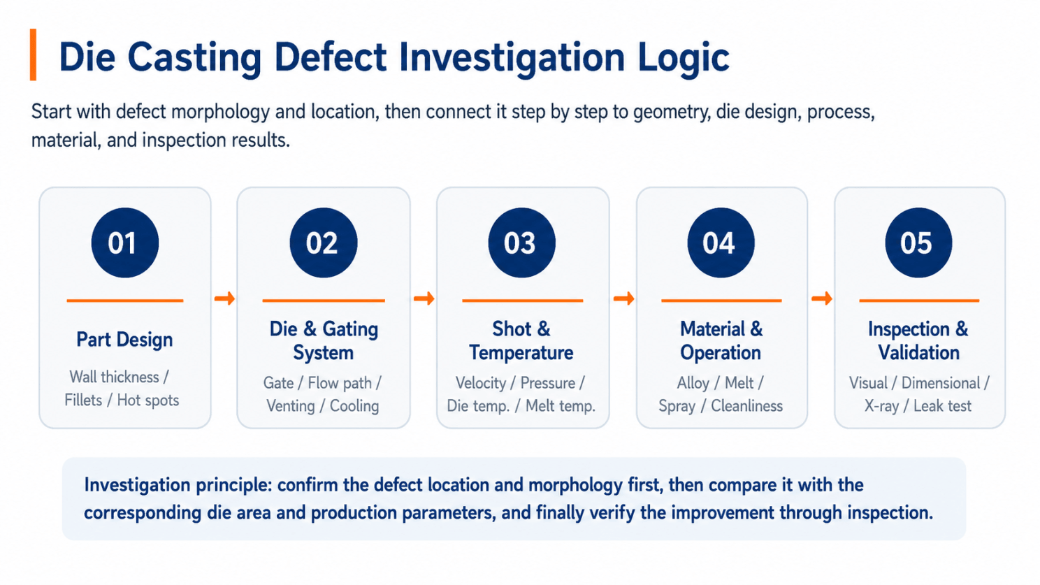
Before examining individual defects, it is useful to establish a structured investigation around five areas.
1. Part Design
Check whether the wall thickness is reasonably uniform and whether abrupt transitions exist between thick and thin sections. Deep cavities, long flow paths, slender ribs, and locally heavy sections may restrict metal flow or create thermal hot spots.
Uniform walls, suitable fillets, and gradual transitions help improve filling and solidification. Excessive wall-thickness variation, sharp corners, and long flow distances may increase the risks of cold shuts, shrinkage porosity, distortion, and localized cracking.
2. Die and Gating System
Gate position, direction, and cross-sectional area directly affect how the molten metal enters and fills the cavity.
The runner, overflow, venting, vacuum system, local cooling circuits, and ejection system should also be reviewed.
A defect visible on the casting surface may not originate from a surface-finishing operation. Flow separation, jetting, air entrapment, premature solidification, or localized die attack may already have occurred during the earliest stage of cavity filling.
3. Shot and Temperature Parameters
Important variables include slow-shot velocity, fast-shot velocity, fast-shot transition position, intensification pressure, melt temperature, die temperature, holding time, and cooling time.
These variables should form a verified and repeatable process window. They should not be adjusted repeatedly based on the result of a single casting. Studies show that fast-shot conditions, transition position, vacuum level, and intensification pressure can affect filling behavior, porosity, and final properties. (MDPI)
4. Alloy and Shop-Floor Operation
Alloy composition, return-material ratio, melt cleanliness, oxide inclusions, plunger lubricant, release-agent concentration, spray volume, and blow-off time may all influence casting quality.
Excess release agent, residual moisture in the cavity, entrained oxide films, or unstable melt handling may contribute to porosity, inclusions, laminations, and surface abnormalities. (MDPI)
5. Inspection and Validation
Not every defect can be detected through visual inspection.
For components with sealing, load-bearing, heat-treatment, welding, or deep-machining requirements, suitable inspection methods may include dimensional inspection, X-ray, CT scanning, leak testing, sectioning, and metallographic analysis.
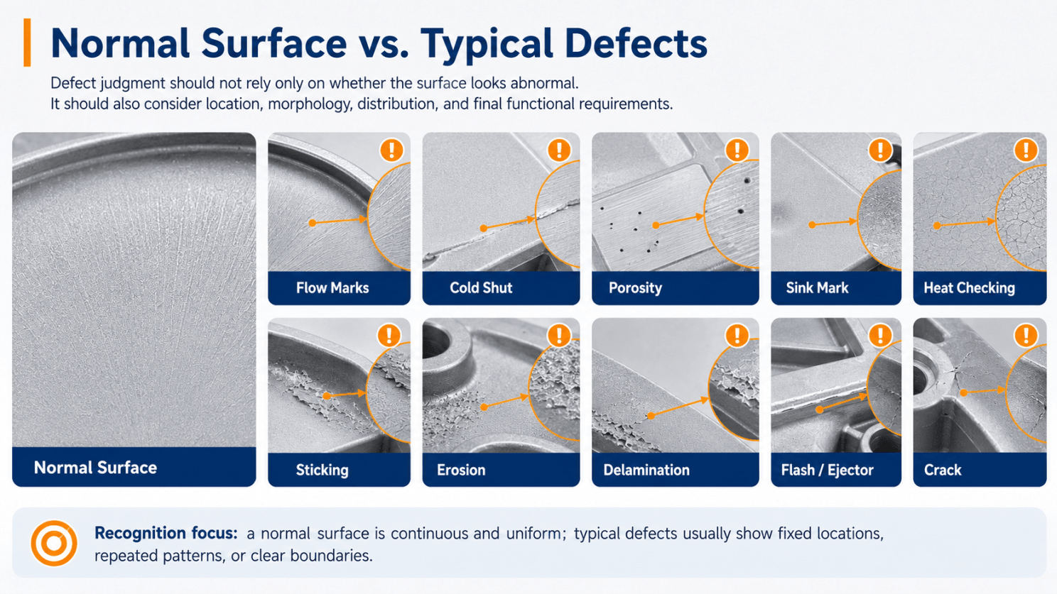
A defect should not be judged only by whether it exists. Its location, size, distribution, and influence on final function must also be considered. The origin of internal porosity cannot be determined reliably from surface appearance alone; gas porosity, hydrogen-related pores, and shrinkage porosity may require CT, sectioning, or metallographic confirmation. (MDPI)
10 Common Aluminum Die-Casting Defects
1. Flow Marks and Surface Flow Lines
Appearance
The casting surface shows streaks, waves, or color differences. Some marks follow the direction of molten-metal flow.
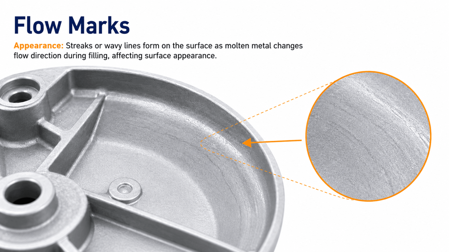
Flow marks normally do not propagate like cracks, but they may affect appearance and indicate instability in cavity filling, die temperature, or release-agent conditions.
Possible Causes
- Low die or melt temperature;
- Unsuitable gate position or filling direction;
- Discontinuous local metal flow;
- Excessive spray or residue on the cavity surface;
- Part geometry that prevents smooth filling;
- Premature formation of a solidified skin at the melt front.
Flow marks are normally related to geometry, gating, temperature, and filling behavior rather than to temperature alone. (ResearchGate)
Investigation Focus
Compare the mark location with the gate, thin-wall areas, and flow-front meeting zones. Then review the die-temperature distribution, spraying condition, and shot curve.
Improvement Direction
Optimize gate position and flow path, improve die thermal balance, and establish repeatable spraying and shot parameters.
Flow simulation may also be used to assess filling sequence, flow-front meeting points, air-entrapment zones, and regions at risk of premature solidification.
2. Cold Shuts and Misruns
Appearance
A cold shut usually appears as a narrow, irregular, depressed line where two metal fronts meet.
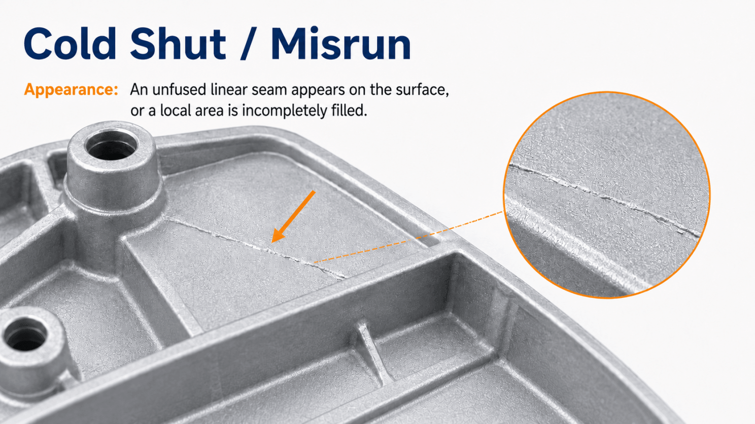
In severe cases, it may form a weak, partially bonded interface that opens during loading, machining, or assembly. A misrun appears as an incompletely formed edge, rib, corner, thin wall, or local feature.
Possible Causes
- Metal fronts are too cold to fuse fully;
- Melt or die temperature is too low;
- The flow path is too long;
- Filling is too slow in thin or complex regions;
- Inadequate venting allows cavity gas to resist filling;
- Gate position, direction, or area is unsuitable;
- An unstable fast-shot transition creates discontinuous filling.
Cold shuts and misruns are closely related to fluidity, temperature, filling continuity, and venting. (ResearchGate)
Investigation Focus
Check whether the defect is concentrated in end-of-fill regions, areas far from the gate, thin walls, or locations where multiple flow fronts meet.
Improvement Direction
Shorten unnecessary flow paths, optimize gates, overflows, and vents, and review the relationship between melt temperature, die temperature, and shot velocity.
3. Gas Porosity and Air Entrapment
Appearance
Gas pores may remain hidden inside the casting or become visible as round or oval holes after machining.
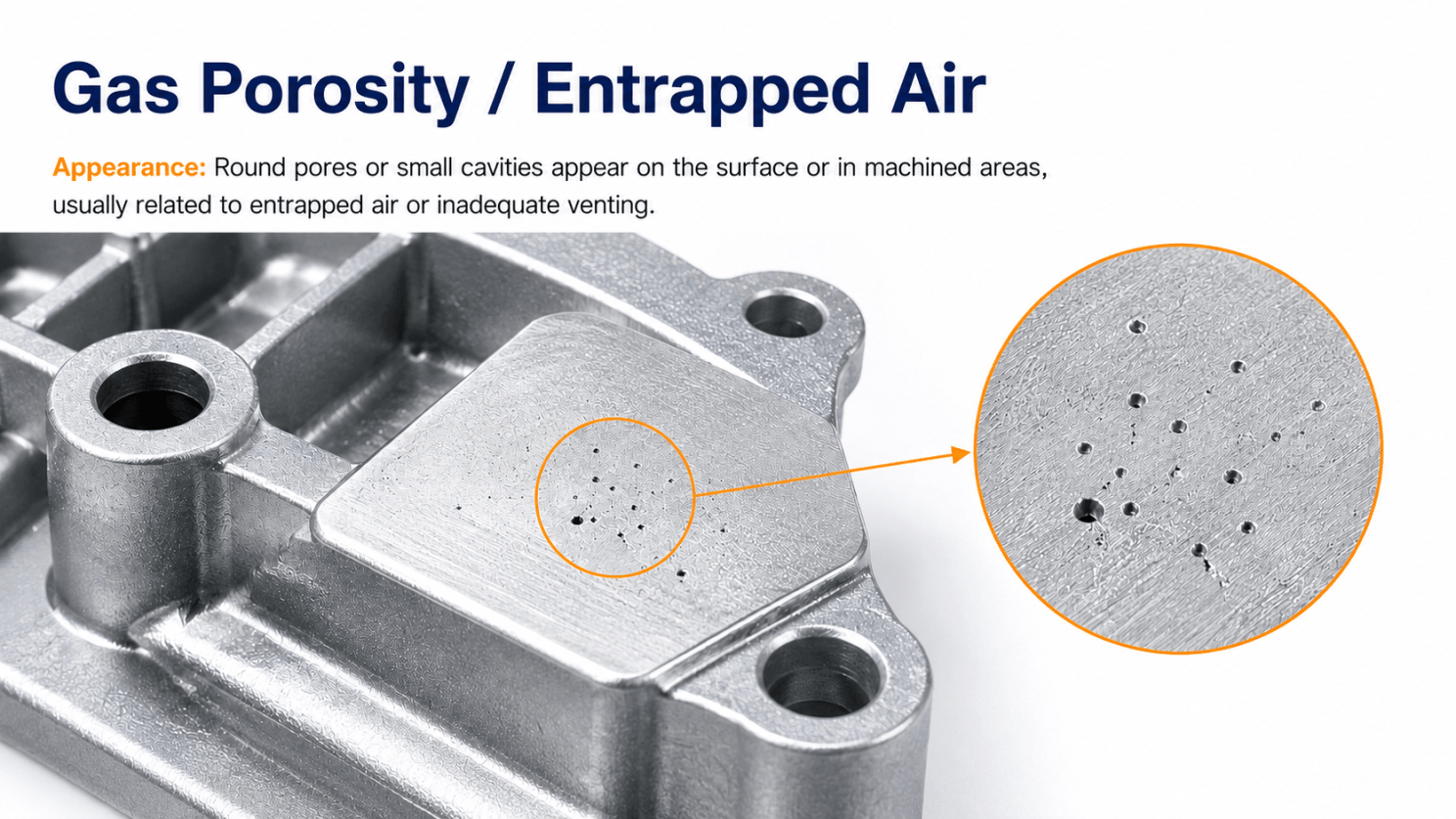
Entrapped-gas pores are often relatively round and smooth, but pore origin cannot be confirmed by appearance alone. Severe porosity may affect leak tightness, mechanical properties, coating, heat treatment, and welding.
Possible Causes
- Air is entrained during high-speed or turbulent filling;
- Venting or vacuum capacity is insufficient;
- Gate design causes jetting, recirculation, or metal-front collision;
- Excess release agent leaves moisture or decomposition products;
- Gas content in the melt is too high;
- The slow-to-fast shot transition is unstable;
- Plunger lubricant or residue in the shot sleeve generates gas.
Air entrapment is closely linked to filling behavior. Turbulent flow may trap gas and fold oxide films into the casting. (MDPI)
Investigation Focus
Use pore morphology, location, distribution, CT data, and sectioning results together.
Porosity at the end of fill suggests a review of venting and vacuum. Porosity near the gate or metal-front collision zone suggests an investigation of jetting, recirculation, and air entrainment.
Improvement Direction
Optimize filling sequence and venting, verify vacuum-system sealing, control release-agent and plunger-lubricant quantities, and stabilize slow shot, fast-shot transition, and intensification.
Under suitable conditions, vacuum combined with intensification pressure can reduce porosity and improve strength and elongation. (MDPI)
4. Shrinkage Porosity and Sink Marks
Appearance
A sink mark normally appears as a smooth depression on the surface of a locally heavy section.
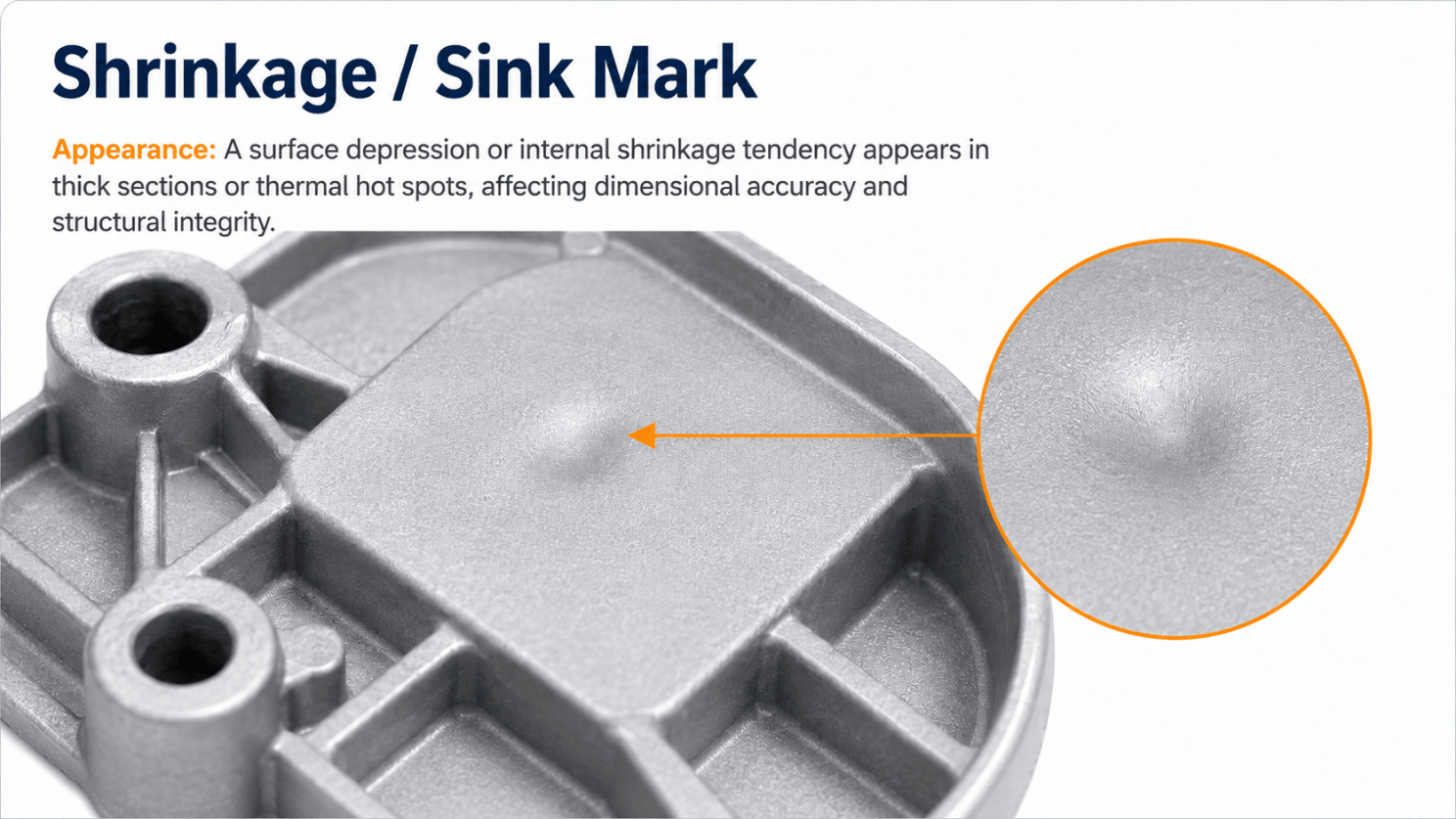
Shrinkage porosity is more often internal and is commonly found around thick walls, rib intersections, boss roots, and other thermal hot spots. Its shape is generally more irregular than entrapped-gas porosity.
Possible Causes
- Excessive wall-thickness variation;
- Local hot spots at heavy sections or rib intersections;
- Intensification begins too late or pressure transfer is insufficient;
- The gate freezes too early for effective pressure feeding;
- Local die temperature is too high;
- Cooling circuits are poorly arranged;
- Holding or cooling time is insufficient;
- Early ejection makes surface sinking or distortion more visible.
Shrinkage defects are associated with solidification contraction, local hot spots, and pressure transfer. They should not be evaluated only by traditional gravity-casting feeding principles. (ResearchGate)
Investigation Focus
Check whether the defect coincides with heavy walls, bosses, rib intersections, or locally hot die regions.
Then review intensification timing, gate-freeze time, holding conditions, and local cooling capacity.
Improvement Direction
Begin with part geometry. Reduce unnecessary material accumulation through coring, material-saving features, and smoother wall transitions.
Also optimize local cooling, gate design, and intensification instead of attempting to hide the problem only by lowering melt temperature.
5. Heat-Checking Imprints and Thermal-Fatigue Marks
Appearance
The casting surface shows a network of fine raised or depressed lines that may gradually expand as the die accumulates more cycles.
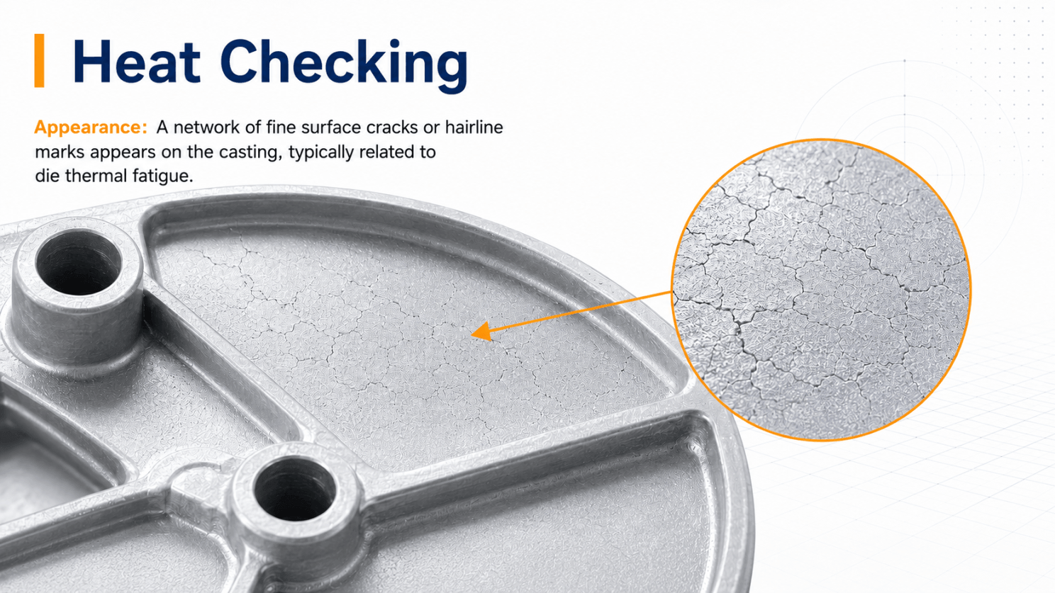
These marks are normally copied from thermal-fatigue microcracks on the die-cavity surface and may also be referred to as heat-check or crazing imprints.
Possible Causes
- Repeated rapid heating and cooling of the die;
- Insufficient or uneven die preheating;
- Excessive localized spraying or cooling;
- Large temperature differences across the cavity surface;
- Unsuitable die material, heat treatment, or surface treatment;
- Extended die service without sufficient maintenance.
Die surfaces are exposed to thermal fatigue, erosion, soldering, and other forms of damage during repeated production cycles. (Karlstads universitet)
Investigation Focus
Check whether the defect becomes more severe at the same location as the shot count increases, and inspect the corresponding cavity surface under magnification.
When the mark repeatedly appears at a fixed position, the die surface should be investigated before further shot-parameter adjustment.
Improvement Direction
Improve die preheating and thermal balance, reduce severe localized thermal cycling, and establish scheduled cavity inspection and maintenance.
Areas with developed heat checking may require polishing, welding repair, or localized surface restoration.
6. Die Soldering and Adhesion Marks
Appearance
The casting surface shows local tearing, roughness, bright areas, dark-gray marks, or material loss.
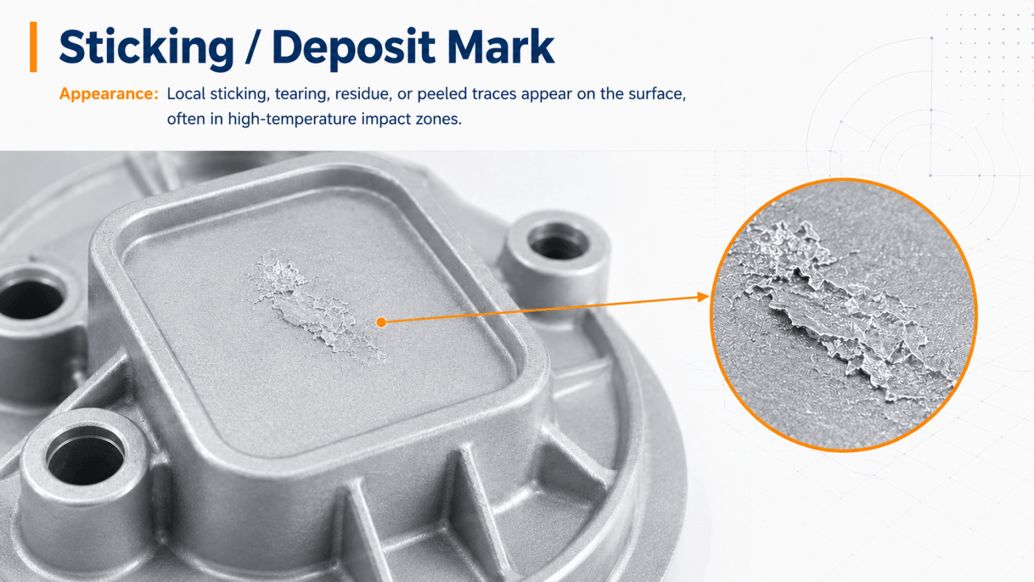
In severe cases, aluminum adheres to the cavity surface and tears away from the casting during ejection. This condition is commonly described as die soldering.
Possible Causes
- Excessive local die temperature;
- Repeated metal impingement on the same die area;
- Interfacial reaction between aluminum and die steel;
- Poor die-surface condition;
- Insufficient or uneven release-agent coverage;
- Inadequate draft angle;
- Excessive local gripping force;
- Unstable ejection.
Die soldering is influenced not only by release agent, but also by local temperature, alloy composition, die material, and interfacial reactions. (Springer)
Investigation Focus
Determine whether the issue is simple release resistance or actual adhesion between the aluminum and die surface.
Check whether the defect is concentrated near gate-impingement areas, deep cavities, side walls, cores, or local die hot spots.
Improvement Direction
Redirect metal impingement, improve local cooling, review the die surface and draft angle, optimize release-agent application, and improve ejection-load distribution.
Increasing spray quantity alone may create additional risks such as gas entrapment, flow marks, and residue.
7. Die Erosion and Localized Roughness
Appearance
The casting shows local pitting, raised texture, roughness, or irregular surface patterns, often near the gate or a direct metal-impingement region.
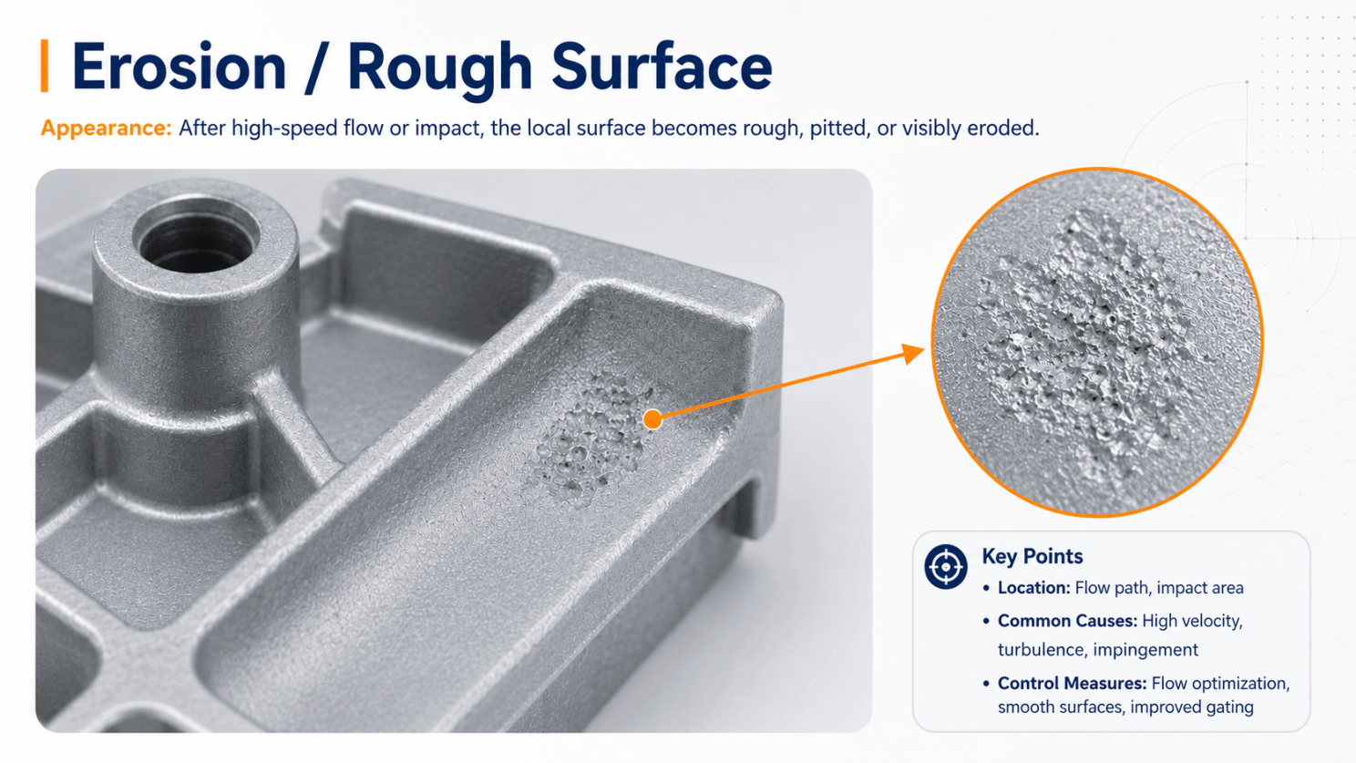
The appearance may reflect die-surface damage and may occur together with soldering, thermal fatigue, or cavity contamination.
Possible Causes
- Gate direction repeatedly exposes a core or cavity area to metal impingement;
- Excessive local flow velocity or shear;
- Unsuitable gate position or cross-sectional area;
- Insufficient die-surface hardness or wear resistance;
- Inadequate cooling in the impact zone;
- Sustained local die overheating;
- Repeated cleaning after soldering damages the cavity surface.
Die erosion, soldering, and thermal damage may interact, so surface roughness alone does not prove a single root cause. (ScienceDirect)
Investigation Focus
Determine whether the defect corresponds to the main impact zone of the incoming metal, and inspect the associated die area for wear, pits, soldered aluminum, or cracks.
Improvement Direction
Adjust the gate position, direction, or area to prevent repeated direct impact at the same location.
Improve local cooling and die-surface protection, and confirm that actual gate velocity remains within the validated process window.
8. Inclusions, Oxide Films, and Laminations
Appearance
The casting contains foreign matter, visible metallic layers, flake-like separation, or discontinuous interfaces.
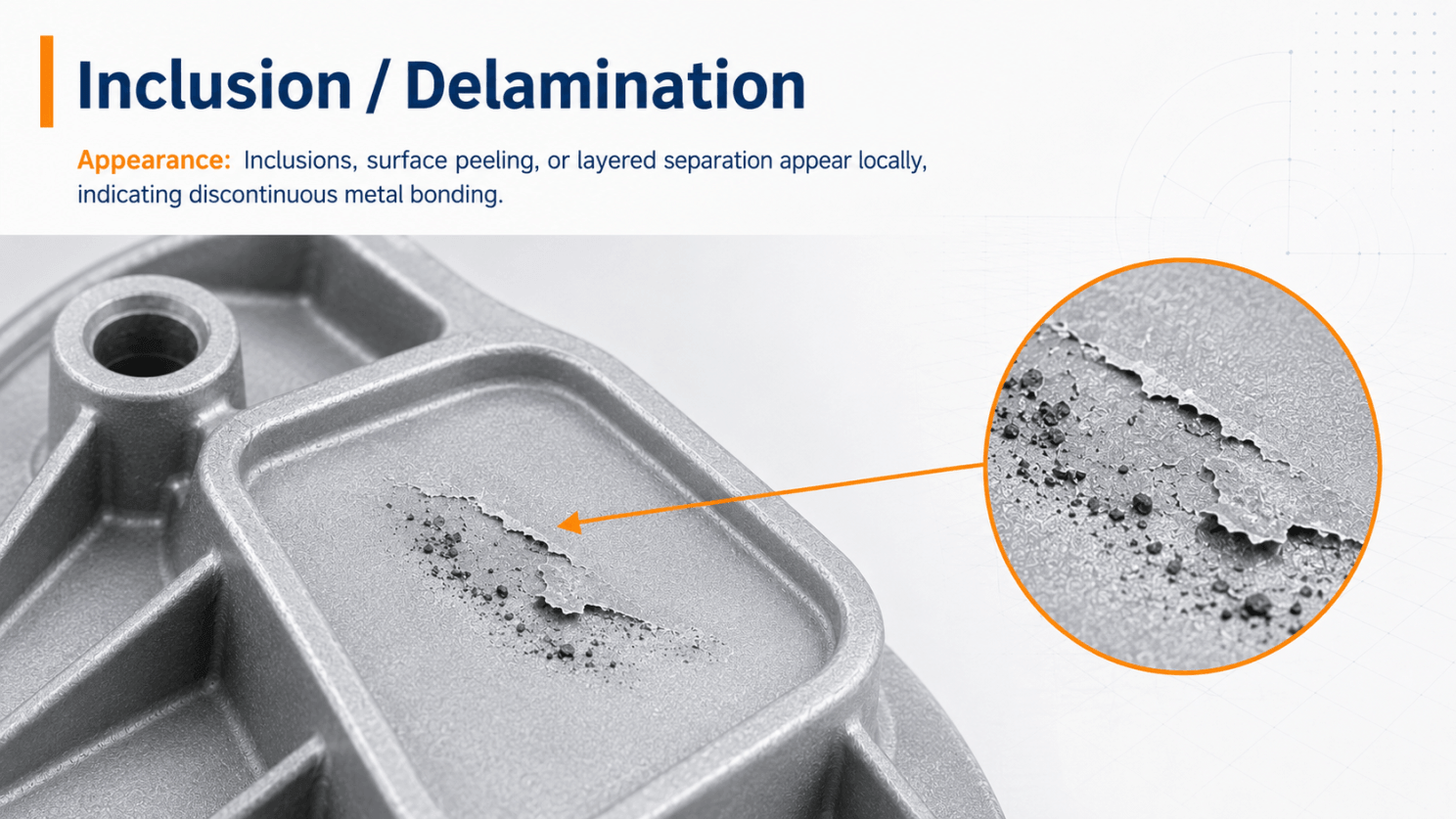
Some defects are difficult to identify visually and become apparent only after sectioning, machining, CT scanning, ultrasonic inspection, or destructive testing.
Possible Causes
- Oxide films on the melt surface become entrained;
- Non-metallic inclusions remain in the melt;
- Residue is present in the ladle, shot sleeve, or cavity;
- Melt transfer or cavity filling is excessively turbulent;
- Multiple flow fronts collide or recirculate;
- Unstable injection creates intermittent filling;
- Cold metal, oxide skins, or contamination enter the cavity.
Aluminum rapidly forms an oxide film when exposed to air. If the film is folded and entrained during handling or filling, it may form a crack-like laminated interface. (Diva Portal)
Investigation Focus
Distinguish between poor melt cleanliness, entrained oxide films, cold material, and incomplete bonding between separate metal fronts.
Surface appearance alone is normally insufficient. Sectioning, metallography, CT, or compositional analysis may be required.
Improvement Direction
Improve melt treatment, skimming, and transfer to reduce the entry of oxide films and inclusions into the shot sleeve.
Optimize the shot profile and gating system to reduce splashing, jetting, collision, recirculation, and discontinuous filling.
9. Flash, Mismatch, and Ejector Marks
Appearance
Flash is a thin layer of excess metal found at the parting line, slide, or insert interface.
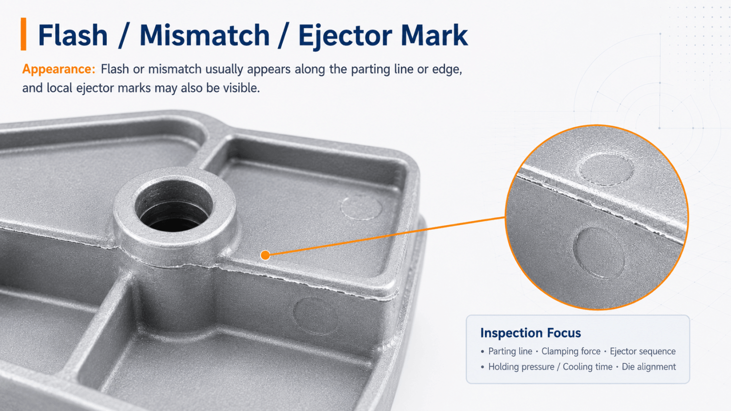
Mismatch appears as an offset or step between adjacent surfaces. Ejector marks are concentrated at ejector-pin locations and may appear as raised, depressed, bright, or locally distorted areas.
Possible Causes
- Insufficient locking force;
- Peak cavity pressure is not matched to die capacity;
- Wear or contamination on the parting surface;
- Excessive clearance around slides or inserts;
- Unstable die alignment or guidance;
- Unequal ejector-pin lengths or worn pin faces;
- Unsuitable ejector location, quantity, or sequence;
- The casting is too hot and weak during ejection.
Flash, mismatch, and ejector marks involve different combinations of machine locking, die fit, alignment, and ejection load. (IJERT)
Investigation Focus
Check whether flash and mismatch occur repeatedly at fixed locations, then inspect the parting surface, inserts, slides, guide components, and locking condition.
For ejector marks, evaluate ejection-force distribution, casting temperature, draft angle, and local gripping force.
Improvement Direction
Repair worn regions, clean the parting surface, correct die alignment and ejection, and confirm that locking force, intensification pressure, and die condition are properly matched.
10. Cracks and Ejection Damage
Appearance
Cracks may be straight, curved, or wavy. They are normally narrow and may continue to propagate under external loading.
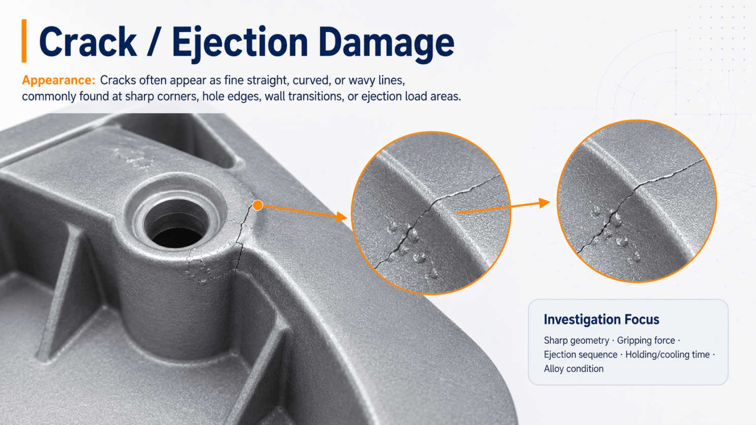
They often occur at abrupt wall transitions, sharp corners, hole edges, deep cavities, slide interfaces, or locations of concentrated ejection force.
Possible Causes
- Unstable alloy composition or excessive impurities;
- Sharp corners or severe wall-thickness transitions;
- Restricted local solidification shrinkage;
- Insufficient holding, dwell, or cooling time;
- Excessive local gripping force;
- Inadequate draft;
- Unsuitable ejector location, quantity, or sequence;
- The casting is too hot and weak during ejection;
- Improper loading during trimming, straightening, or handling.
Investigation Focus
Determine whether the crack formed during solidification, die opening, ejection, trimming, straightening, or later handling.
When the crack aligns with an ejector pin, slide, deep cavity, hole edge, or sharp structural feature, focus on geometry and ejection loading rather than adjusting melt temperature alone.
Improvement Direction
Improve wall transitions and fillets, reduce ejection resistance, verify alloy and temperature conditions, and set suitable holding, cooling, opening, and ejection times.
Defect Control Should Not Begin with Production Scrap
Die-casting defects rarely have only one cause.
The same flow mark may result from low die temperature, gating, release-agent residue, or part geometry. A similar internal void may originate from entrapped air, dissolved gas, solidification shrinkage, or an entrained oxide film.
For this reason, establishing a complete risk-control path early in the project is more valuable than adjusting parameters only after defects appear.
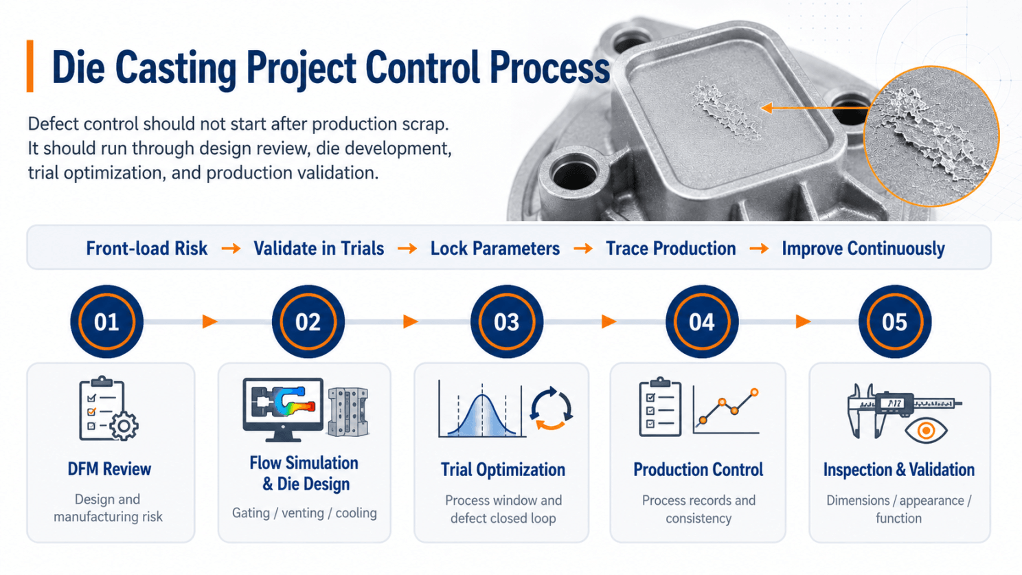
1. Conduct a DFM Review Before Tooling
Review wall thickness, fillets, draft, deep cavities, bosses, ribs, and machining allowance to identify structures that may hinder filling, solidification, or ejection.
Small design changes, such as improving wall uniformity, fillets, and feature locations, may improve metal flow and reduce tooling and machining risk.
2. Analyze Metal Flow During Die Design
Evaluate the gate, runner, overflow, venting, vacuum system, and cooling layout against the part geometry.
The objective is to reduce unnecessarily long flow paths, end-of-fill air entrapment, metal-front collisions, and local thermal hot spots.
Flow simulation cannot replace physical trials, but it can help identify unsuitable filling sequences, air-entrapment locations, and temperature distributions before tooling is finalized. (MDPI)
3. Establish a Stable Process Window Through Trials
The objective of a trial is not simply to produce a few parts that look acceptable.
Die temperature, melt temperature, shot profile, fast-shot transition, vacuum, intensification pressure, and cooling conditions should be recorded.
The process should then be evaluated across multiple shots to determine whether it remains stable under normal production variation.
4. Define Inspection Around Part Function
Cosmetic parts, pressure-tight parts, structural components, heat-treated parts, and deeply machined components do not have the same defect-acceptance requirements.
Inspection should therefore be designed around final function rather than applying an identical inspection plan to every die casting.
5. Feed Defect Results Back into the Die and Process
Each defect investigation should generate a traceable record covering defect location, shot number, machine settings, die condition, root-cause assessment, corrective action, and validation result.
This closed-loop approach turns the lessons from a trial or production abnormality into a repeatable basis for stable production.
From Finding Defects to Controlling Risk Earlier
The strengths of die casting include high forming efficiency, good dimensional consistency, and suitability for volume production.
To achieve those advantages consistently, engineering control must connect product design, die development, trial validation, production monitoring, and quality inspection.
At Mastars, our focus goes beyond forming an aluminum part in a die.
Planning a new aluminum die-casting project, or looking to reduce production risks such as porosity, cold shuts, sink marks, and die soldering?
Contact Mastars. From early DFM, flow and die design review, and trial optimization to machining, surface finishing, and quality validation, we provide connected engineering and manufacturing support throughout the project.
Get in touch with us to review the key manufacturing risks in your project. Follow Mastars for more engineering insights, process knowledge, and manufacturing practices.
Save time, save money. Mastars, where great ideas are built.
Hot Articles

Hot Tags
Stay Connected!


Manufacturing on Demand
Please fill in the following information to obtain plan details (information is confidential and not disclosed publicly), we will contact you within 24 hours, please keep your phone available!
Upload a 3D/2D model to see instant pricing, lead time, and DFM feedback.