



Engine Component Manufacturing Through Three Processes


From Separate Parts to One Engine Assembly
Mastars supported a customer engine-component project combining CNC machining, sheet metal fabrication, and welding to produce an assembly with an AISI 431 stainless steel base plate and an AISI 304 perforated cylinder.
The base plate provides the mounting structure, while the perforated cylinder forms the surrounding thin-wall geometry. Each part follows a different manufacturing route, but both must meet the assembly requirements.
The drawing specifies +0/−0.05 mm for an axial dimension. This requirement connects the accuracy of the machined base, the geometry of the fabricated cylinder, and their final relationship after welding.
The manufacturing challenge is to preserve the required geometry as separate parts become one assembly.
Precision Must Continue Through Joining
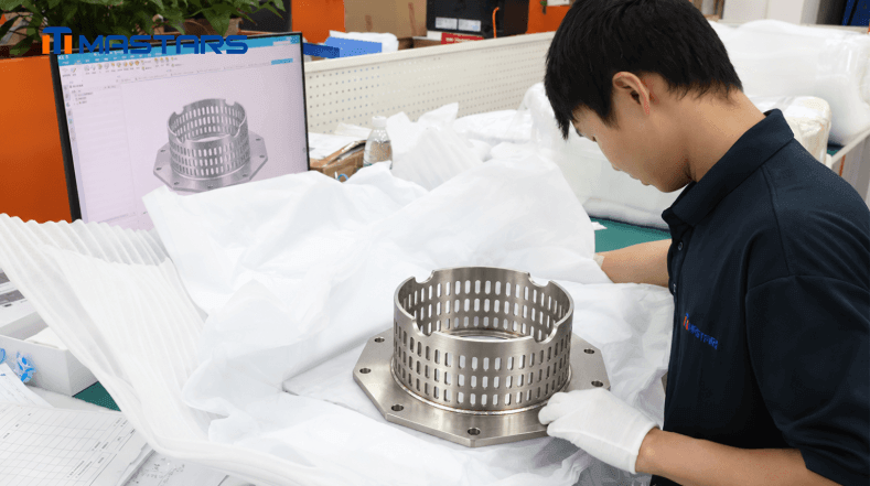
The specified unilateral tolerance allows no increase above the nominal dimension and a maximum reduction of 0.05 mm.
CNC machining establishes the base plate’s features and reference surfaces. Sheet metal fabrication establishes the cylinder’s profile and joining edge. Assembly positioning brings these geometries together, while welding can introduce dimensional movement.
The completed assembly must meet the drawing after welding and fixture release. Accurate individual parts provide the foundation, but their final relationship also depends on fit-up, positioning, and joining.
For the customer, coordination between processes is therefore as important as the execution of each operation.
Two Materials, Three Manufacturing Roles
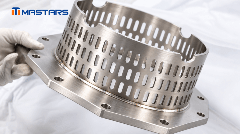
The project specifies AISI 431 for the base plate and AISI 304 for the perforated cylinder. Material identification must remain traceable throughout machining, fabrication, and joining.
CNC machining establishes the mounting references. The base plate’s mounting features and reference surfaces provide the foundation for subsequent assembly positioning and dimensional verification.
Sheet metal fabrication creates the cylindrical structure. The perforated cylinder requires control of its profile, joining edge, and opening geometry. Its thin-wall structure also makes handling and local deformation relevant to assembly preparation.
Welding connects the prepared components. Fit-up, fixture strategy, and welding sequence must support the finished dimensional requirements. The procedure must suit the specified material grades, material condition, and customer requirements.
Mastars’ engineering focus is to connect these operations around the completed component. Machining datums, sheet metal geometry, and welding references need to remain consistent throughout the manufacturing route.
One-Dimensional Plan Across the Process
Manufacturing planning starts with the critical finished dimension. It identifies which surfaces establish that dimension, how the parts are positioned, and how the completed assembly will be measured.
The references established during CNC machining need to remain usable during cylinder positioning. The fabricated cylinder must fit the base consistently, while the fixture must provide welding access and allow the released assembly to be checked.
The coordinated route follows five stages:
Drawing and material review identifies the controlled dimensions, reference surfaces, and material assignments.
CNC machining establishes the base plate’s mounting features and assembly references.
Sheet metal fabrication prepares the perforated cylinder and controls the geometry relevant to joining.
Positioning and welding align the components and connect them using a suitable procedure that accounts for dimensional movement.
Final verification checks the specified dimensions and relevant mounting relationships after welding and fixture release.
Any need for post-weld finish machining should be determined through process validation. This decision depends on the dimensional result and assembly requirements.
Customer Value in Connections
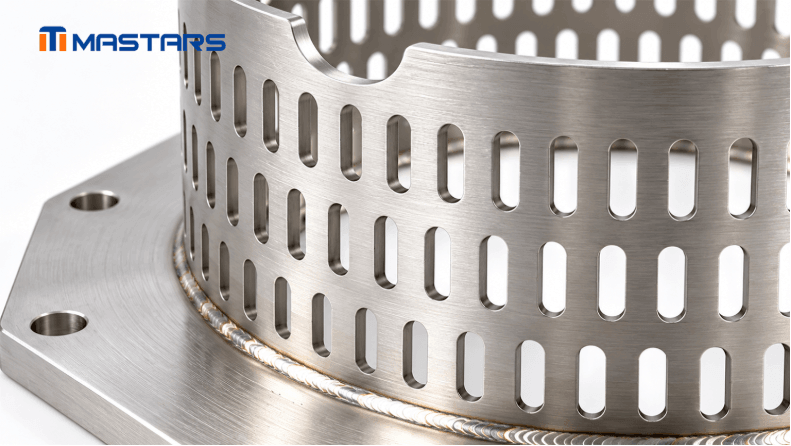
The customer value comes from keeping the finished component’s requirements consistent across three manufacturing processes.
The specified +0/−0.05 mm axial tolerance provides a common dimensional target for machining, fabrication, positioning, and inspection.
Traceability of the two specified stainless steel grades connects each component with its material and joining requirements.
Three coordinated processes — CNC machining, sheet metal fabrication, and welding — work toward the same finished assembly requirements.
Clearer process handoffs help preserve reference surfaces and assembly requirements between operations.
Verification of the completed assembly — acceptance focuses on the component after joining and fixture release.
Where the Same Manufacturing Logic Applies
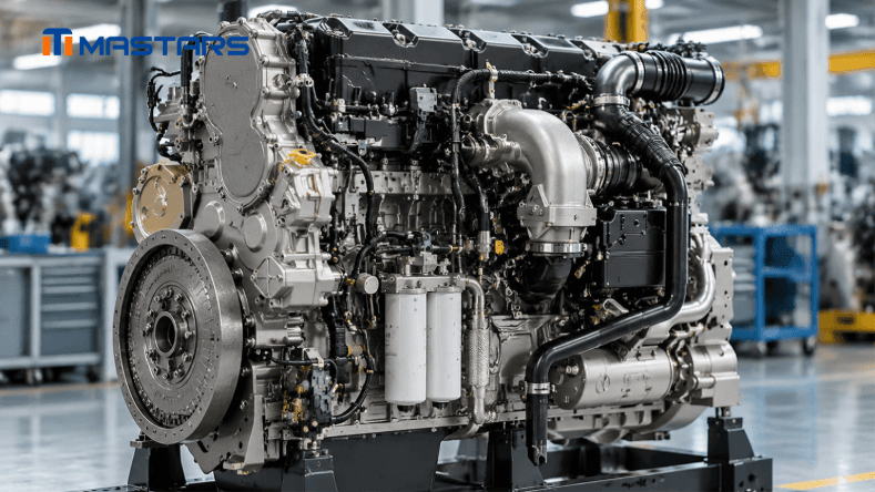
The same approach is relevant wherever a fabricated thin-wall structure joins a CNC-machined mounting interface.
Automotive and Powertrain Engine auxiliary assemblies, metal shields and mounting structures.
Power Generation: Generator-set components, ventilation assemblies and equipment guards.
Industrial Machinery: Cylindrical enclosures, perforated guards and support assemblies.
Process Equipment: Perforated sleeves, screen supports and welded mounting components.
Does your manufacturing route carry the critical dimension through machining, fabrication, and welding?
Share your drawings with Mastars to discuss a coordinated route from separate components to a verified assembly.

Mastars, the most trusted one-stop manufacturing services provider for low-volume production worldwide!
Hot Articles
Hot Tags
Stay Connected!


Manufacturing on Demand
Please fill in the following information to obtain plan details (information is confidential and not disclosed publicly), we will contact you within 24 hours, please keep your phone available!
Upload a 3D/2D model to see instant pricing, lead time, and DFM feedback.