



Plastic Tooling: Principles, Manufacturing Process, Materials, Parameters and Industrial Cases


Plastic tooling, commonly referred to as plastic injection molds, is the core foundational tool for mass-producing standardized plastic components in modern manufacturing industries. As the carrier that shapes molten thermoplastic materials into designated geometric structures, plastic tooling directly determines the dimensional accuracy, surface quality, production efficiency and overall service life of final plastic products. Compared with metal tooling used for die casting and stamping, plastic tooling features flexible structural design, diversified material options and customizable processing parameters, which can adapt to simple daily plastic parts and complex multi-functional structural components. This paper systematically elaborates on the working principle of plastic tooling, sorts out the complete manufacturing workflow of injection molds, analyzes the characteristics and applicable scenarios of mainstream tooling materials, lists standardized molding parameter data for matched plastic materials, and presents two typical industrial application cases. The research aims to help product engineers and mold manufacturers understand the core attributes of plastic tooling, optimize mold design schemes, and reduce potential risks in mass production.(Word Count: 2485)
1. Introduction
With the rapid development of lightweight manufacturing, plastic parts have been widely applied in consumer electronics, automotive manufacturing, medical devices, household appliances and packaging industries. All high-volume plastic products relying on injection molding, compression molding and blow molding require customized plastic tooling to realize standardized and repetitive production. Plastic tooling covers multiple types of molds such as injection molds, blow molds and compression molds, among which injection mold tooling accounts for more than 80% of the overall market share due to its strong compatibility and high molding efficiency (MoldAlliance, 2026).
Many manufacturing practitioners confuse plastic tooling with ordinary mechanical parts and ignore the importance of systematic mold design and material selection. In actual production, unreasonable tooling structure, improper mold material selection and mismatched process parameters will directly lead to common defects including part warpage, surface bubbles, short shots and burrs, increasing defective product rates and raising long-term operating costs. A high-quality plastic tooling can not only ensure the dimensional consistency of tens of thousands of molded parts, but also shorten the single-cycle molding time and reduce the energy consumption of injection equipment.
To solve the pain points in tooling selection and design, this article comprehensively discusses the core theories and practical application knowledge of plastic tooling. It starts with basic working principles, further explains end-to-end mold manufacturing procedures, analyzes tooling material classification and matching rules, provides optimized molding parameters for different material combinations, and verifies the practical value of high-quality plastic tooling through real engineering cases.
2. Working Principle of Plastic Tooling
2.1 Core Operating Mechanism
The essential working principle of plastic injection tooling is to constrain, shape and cool molten plastic materials through a closed and precise metal cavity structure. A complete set of plastic injection tooling is composed of a fixed half and a moving half. After the mold is fully locked, the two halves form an enclosed cavity with the same shape and size as the target plastic part. During the injection phase, molten plastic is injected into the cavity through the sprue and runner system under high pressure; the tooling bears the impact force and internal pressure generated by fluid plastic and limits the flow range of the colloid to complete shape filling.
Beyond basic shaping functions, modern plastic tooling integrates independent cooling systems, ejection systems and venting systems to realize collaborative molding. The built-in cooling water channels control the mold surface temperature to balance the cooling speed of plastic parts and eliminate internal stress. The vent slots discharge air accumulated inside the cavity to avoid silver lines and scorch marks on the part surface. After the plastic is completely cooled and solidified, the ejection system pushes finished parts out of the cavity to complete a full molding cycle.
2.2 Basic Tooling Structure Composition
Standard plastic injection tooling consists of six core modules. The first module is the gating system, including sprue, runner and gate, which controls the flow direction and filling speed of molten plastic. The second module is the molding component, namely the core and cavity insert, which directly determines the geometry of finished products and is the most wear-prone part of the entire tooling. The third module is the cooling system composed of circulating water pipes, which undertakes the cooling and temperature regulation work. The fourth module is the venting system, used to exhaust trapped air and volatile gas generated by high-temperature plastic. The fifth module is the ejection system containing ejector pins and ejector plates, responsible for demolding finished parts. The last module is the guiding and positioning assembly, which ensures the alignment accuracy of fixed half and moving half to prevent part flash caused by mold misalignment.
3. Complete Manufacturing Process of Plastic Tooling
The development and manufacturing of plastic tooling is a rigorous multi-stage process, which involves design simulation, rough machining, finish machining, surface treatment and trial molding. The whole cycle ranges from two weeks for simple aluminum molds to eight weeks for complex multi-cavity steel molds. The detailed procedures are divided into six steps:
Step 1: DFM Analysis and Tooling Design. Engineers analyze the 3D drawing of target plastic parts, evaluate demolding feasibility, wall thickness rationality and undercut structure distribution. After completing the design for manufacturing (DFM) report, designers draw the overall mold structure, cooling pipeline layout and gating system layout with CAD software. Meanwhile, mold flow simulation is conducted via CAE tools to predict potential defects such as uneven cooling and warpage during the molding stage.
Step 2: Tooling Material Cutting and Rough Machining. According to design requirements, select qualified mold steel or aluminum alloy blanks, and cut raw materials into specified sizes. Carry out rough milling on core and cavity inserts through CNC machining equipment to remove redundant materials and initially form the basic contour of the cavity while reserving a margin of 0.2mm to 0.5mm for finish machining.
Step 3: Finish Machining and Precision Processing. Use high-precision milling machines, wire cutting machines and EDM spark machines to process fine structures such as deep grooves, tiny holes and undercuts on the mold insert. This step directly affects the dimensional tolerance of finished plastic parts, and the overall machining accuracy needs to be controlled within ±0.01mm for high-precision products.
Step 4: Surface Treatment and Hardening. Carry out surface polishing, texture etching and anti-corrosion treatment on the molding surface. Polishing is used to produce glossy parts, while texture etching can create matte and patterned surfaces. For steel molds, vacuum quenching and tempering treatment are performed to improve surface hardness and wear resistance, extending the service life of the tooling.
Step 5: Tooling Assembly and Debugging. Assemble all components including inserts, cooling pipelines, ejector pins and guide posts in sequence. After assembly, calibrate the mold clamping gap and positioning accuracy to eliminate flash risks caused by poor fitting between mold halves.
Step 6: Trial Molding and Iterative Optimization. Install the finished tooling on an injection molding machine for trial production. Collect sample parts, detect surface quality and dimensional data, adjust runner size, cooling parameters and vent slot depth according to existing defects, and repeat trial molding until the samples fully meet customer standards.
4. Mainstream Plastic Tooling Materials and Characteristics
Tooling material selection is the most critical link in the early stage of mold development, which mainly depends on production batch, plastic material corrosiveness and surface quality requirements. Plastic tooling materials are divided into two major categories: aluminum alloy materials for low-to-medium batch production and mold steel materials for high-volume mass production. Different materials vary greatly in hardness, service life, manufacturing cost and surface processing performance.
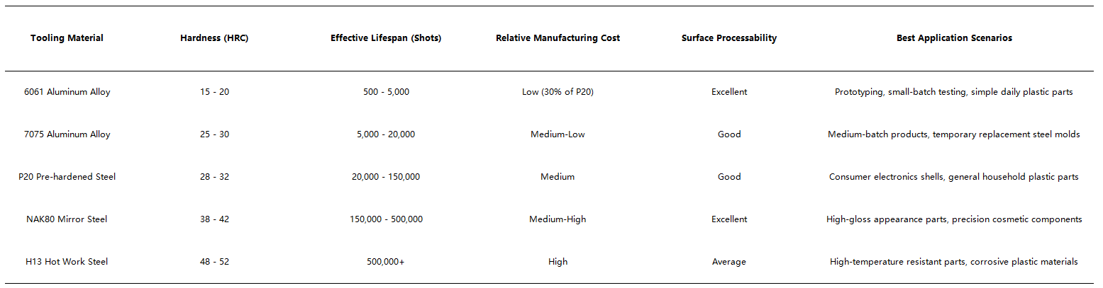
Table 1: Performance Parameters and Application of Common Plastic Tooling Materials
Aluminum alloy tooling has the advantages of low cost and short processing cycle, and its thermal conductivity is 3-5 times higher than that of steel materials, which can effectively shorten the cooling time of plastic parts and improve production efficiency. However, low hardness leads to poor wear resistance, so it is only suitable for small and medium batches. Mold steel tooling has high hardness and strong anti-corrosion and anti-wear capabilities; hardened steel such as H13 can adapt to corrosive plastics containing glass fiber and flame retardant additives, becoming the mainstream choice for long-term mass production projects.
5. Key Process Parameters for Plastic Tooling Operation
After the completion of tooling manufacturing, matching injection parameters according to tooling material and plastic resin is essential to give full play to tooling performance. Mold temperature is the core parameter controlled by plastic tooling, which directly affects the fluidity of molten plastic, surface finish and cooling shrinkage rate. The following table summarizes the optimal mold temperature and supporting injection parameters for mainstream plastic resins under different tooling types, which can be directly used for mass production parameter setting.

Table 2: Recommended Operating Parameters for Plastic Tooling & Resin Matching
For aluminum tooling, the mold temperature should not exceed 90°C for a long time, otherwise it will cause thermal deformation of the cavity and reduce tooling accuracy. For glass fiber reinforced plastics with strong wearability and corrosiveness, H13 hardened steel tooling must be adopted to avoid rapid surface wear and cavity erosion. Meanwhile, appropriately extending the holding time can compensate for plastic shrinkage gaps and reduce the warpage defect closely related to tooling cooling uniformity.
6. Industrial Application Cases of Plastic Tooling
6.1 Case 1: Aluminum Tooling for Disposable Cosmetic Packaging Shell
6.1.1 Project Background
A cosmetic brand launched a new mini lipstick packaging shell. The product is made of transparent PP material with simple cylindrical structure and smooth outer surface. The project belongs to seasonal limited-edition products with a total planned output of 12,000 pieces. The brand needs to complete production within 15 days and control the overall mold development cost below $1,500, so high-cost traditional steel molds are not suitable for this temporary project.
6.1.2 Tooling Design and Solution
The mold manufacturer customized a double-cavity tooling adopting 7075 high-strength aluminum alloy as the base material. Compared with steel molds, the aluminum tooling shortened the processing cycle from 28 days to 7 days and reduced the development cost to $1,180. In terms of structural design, a direct side gate was adopted to ensure the smoothness of the transparent shell surface; the cooling water channel adopted a surround-type layout to improve cooling efficiency and eliminate surface flow marks.
According to the parameter standard in Table 2, the production parameters were set as follows: mold temperature 42°C, melt temperature 200°C, injection pressure 70MPa, cooling time 14 seconds. In the trial molding stage, aiming at the slight warpage of the shell top, the technical team adjusted the local water channel temperature to balance the cooling speed of the inner and outer walls of the part, and successfully solved the quality problem.
6.1.3 Project Outcome
The aluminum plastic tooling successfully completed the batch production of 12,000 lipstick shells within the specified cycle. The surface smoothness and dimensional tolerance of finished products fully met the brand’s packaging standards, and the defective rate was controlled below 1.1%. After the completion of the project, the tooling can be stored for repeated use in subsequent small-batch replenishment. This case proves that aluminum plastic tooling is the optimal cost-effective solution for short-cycle, medium-batch temporary products.
6.2 Case 2: High-precision Steel Tooling for Automotive Electrical Connector
6.2.1 Project Background
A new energy vehicle supporting manufacturer needs to produce special electrical connector shells. The parts are made of PA66 reinforced plastic containing 30% glass fiber, featuring complex reinforced ribs, multiple mounting holes and undercut structures. The connector needs to adapt to high-temperature engine compartment environment, requiring high structural strength and dimensional stability. The annual stable order demand reaches 600,000 pieces, and the service life of the tooling needs to support at least 500,000 molding shots.
6.2.2 Tooling Design and Solution
Considering the high wearability of glass fiber materials and long-term mass production demand, the technical team abandoned aluminum alloy and P20 steel, and selected integral H13 hot work hardened steel to manufacture the four-cavity injection tooling. The core and cavity inserts were quenched to increase surface hardness up to 50HRC, which could effectively resist the erosion and wear caused by glass fiber plastic.
In terms of parameters, the mold temperature was set to 95°C, the melt temperature to 275°C, and the cooling time was extended to 32 seconds to release internal stress. In addition, an independent high-precision venting system was added to the tooling to exhaust volatile gas generated by high-temperature nylon materials and avoid scorch defects on the surface of precision ribs.
6.2.3 Project Outcome
The H13 steel plastic tooling has been put into continuous mass production for 10 months, with a cumulative output of more than 520,000 qualified connectors. The tooling cavity has no obvious wear and deformation, and still maintains the original molding accuracy. The four-cavity structural design greatly improves production efficiency, reducing the single-piece manufacturing cost by 27% compared with the previous single-cavity P20 steel mold. This case verifies that hardened steel plastic tooling has irreplaceable advantages in high-volume and high-precision industrial component production.
7. Conclusion
As the core carrier of plastic part manufacturing, plastic tooling determines the upper limit of product quality and production efficiency. Its working principle relies on closed cavity shaping and circulating temperature control; the complete manufacturing process covers design simulation, precision machining, surface treatment and trial molding iteration. Tooling materials range from low-cost aluminum alloys for prototype and small-batch production to high-hardness hardened steel for long-term mass production, and engineers need to select materials reasonably based on output volume and plastic material characteristics.
Combined with the two practical cases of cosmetic packaging and automotive connectors, it can be concluded that there is no universal best plastic tooling, only the most suitable one. Small-batch seasonal products prioritize high-cost-performance aluminum tooling; high-precision and high-volume industrial parts need to adopt anti-wear hardened steel tooling and match targeted injection parameters. In the future, with the popularization of 3D printed conformal cooling channels and intelligent temperature control technology, plastic tooling will further reduce molding defects and shorten production cycles, and become a more critical core support for the global plastic manufacturing industry.
References
[1] MoldAlliance. Ultimate Guide to Plastic Injection Tooling Design[EB/OL]. 2026.
[2] GlobalMold Tech. Material Selection Criteria for Injection Mold Tooling[EB/OL]. 2025.
[3] Plastic Processing Industry Association. Standard Operating Parameters for Injection Molds[EB/OL]. 2026.
[4] AutoMold Solutions. Hardened Steel Tooling Application for Glass-filled Nylon Parts[EB/OL]. 2025.
Hot Articles
Hot Tags
Stay Connected!


Manufacturing on Demand
Please fill in the following information to obtain plan details (information is confidential and not disclosed publicly), we will contact you within 24 hours, please keep your phone available!
Upload a 3D/2D model to see instant pricing, lead time, and DFM feedback.