



How to Reduce Cycle Time in Injection Molding for Thick-Walled Automotive Lighting Parts


Thick-walled automotive lighting parts, including light guides and optical lenses, can require long injection molding cycles because their internal heat takes time to dissipate. Cooling may account for 60%–80% of the total cycle in these applications. The most effective improvements usually come from reducing unnecessary material thickness, improving heat removal from local hot spots, and adjusting process settings without compromising dimensional stability or optical performance.
Shortening the cooling timer alone does not remove heat from the part. If the component is ejected too early, sink marks, internal voids, warpage, residual stress, or dimensional drift may follow. A more reliable approach is to identify what limits the current cycle, address that constraint, and verify the result under repeatable molding conditions.
The sections below focus on how to identify the bottleneck, choose an appropriate cooling improvement, and validate cycle-time reductions before production.
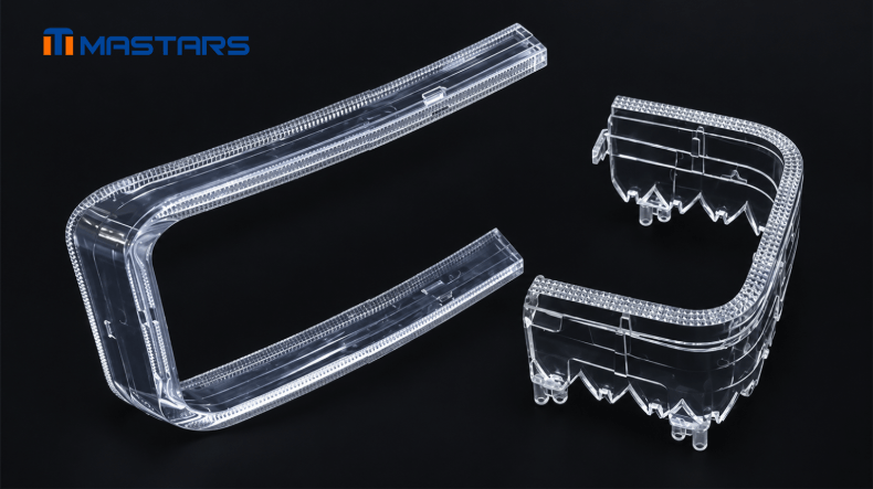
Transparent light-guide parts with complex curves and thick sections require uniform cooling
Injection Molding Cycle Time: Find the Actual Bottleneck
The first step in reducing injection molding cycle time is to determine which stage limits the process. For thick-walled parts, cooling is often the main constraint, but packing, screw recovery, mold movement, or ejection can also affect the overall cycle. Optimizing a stage that does not limit production may produce little improvement in actual output.
| Cycle stage | What to check | Potential improvement |
|---|---|---|
| Filling and packing | Filling stability, packing response, gate freeze | Optimize filling and avoid unnecessary packing time |
| Cooling | Thick sections, local hot spots, mold temperature distribution | Improve part geometry and heat transfer |
| Screw recovery | Whether plasticizing finishes before the mold is ready | Coordinate screw recovery with the rest of the cycle |
| Mold opening and closing | Mold travel, core movements, ejection sequence | Reduce unnecessary movement where the tooling allows |
| Ejection | Part deformation, sticking, ejection reliability | Establish the shortest safe and repeatable ejection sequence |
Start with the actual machine cycle data rather than assuming cooling is responsible for every delay. Compare the time spent in each stage and check whether operations overlap. For example, if screw recovery finishes well before cooling ends, improving plasticizing time alone may not shorten the cycle. If cooling is already the longest stage, mold temperature distribution and the last-to-cool areas deserve closer attention.
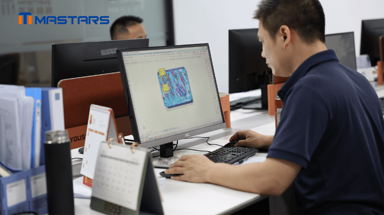
Mastars DFM engineers review part design, flow considerations, and manufacturability to identify potential molding risks before tooling.
Why Thick-Walled Automotive Lighting Parts Take Longer to Cool
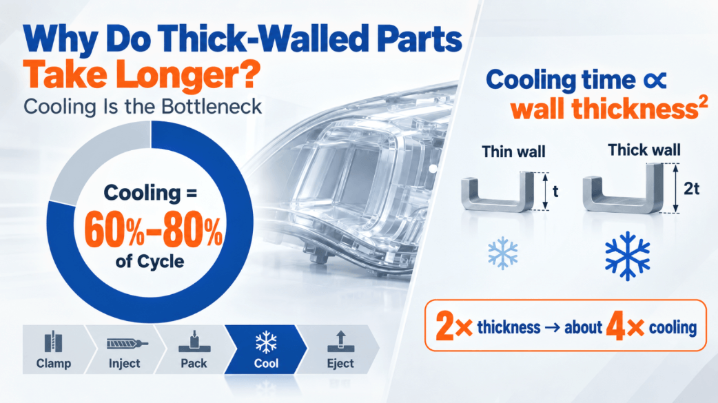
Thick-walled components retain heat longer because heat must travel from the interior of the plastic to the mold surface before it can be removed. Under similar material and processing conditions, cooling time can be approximated as proportional to the square of wall thickness. Doubling wall thickness may therefore require roughly four times the cooling time, although actual results depend on geometry, material properties, and mold conditions.
This relationship makes local geometry especially important. A single 10 mm boss or thick intersection may remain hot long after the surrounding walls have cooled sufficiently. That section can determine when the entire part can be ejected, even if most of the component is relatively thin.
Automotive lighting parts add another constraint: dimensional stability alone may not be enough. Light guides and optical lenses can also require control of transparency, surface quality, internal voids, residual stress, and optical performance. A surface that appears solid does not necessarily mean the center has cooled sufficiently. Ejecting the part too early may save time on one cycle but introduce defects or dimensional changes that appear later.
For these parts, the first design question is whether all the material in a thick section is structurally necessary. If the geometry is already fixed, the next step is to identify where the remaining heat is concentrated and determine whether the mold can remove it more effectively.
Part Design and Mold Cooling: Address the Heat Source First
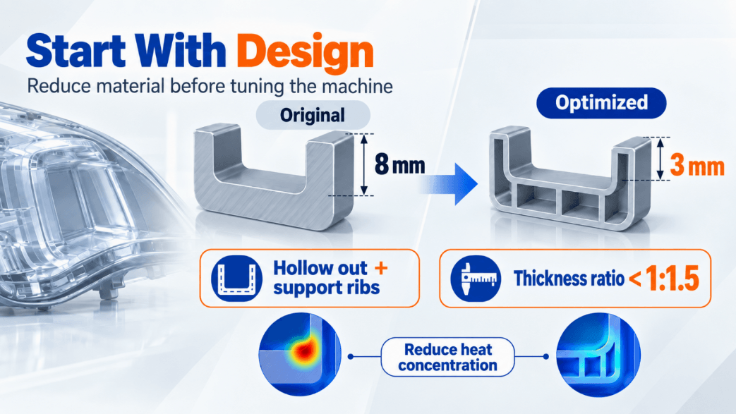
When the design can still be changed, reducing unnecessary material thickness is often a more effective starting point than compensating for excessive thickness through process settings. Where structural and functional requirements allow, solid sections can sometimes be replaced with hollowed geometry or properly designed ribs. For example, reducing a local wall section from 8 mm to 3 mm can substantially reduce the amount of material that needs to release heat during each cycle.
Wall thickness should also transition as uniformly as practical. A thickness ratio around 1:1.5 or less is a useful design reference for reducing severe thermal concentration, but it is not a universal acceptance rule. Structural loads, optical requirements, flow behavior, and the geometry of the part may limit how much the design can change. Where a thick section cannot be reduced, the tooling design should account for the resulting thermal load.
Once the geometry is largely fixed, inspect the cooling system around the last-to-cool areas. Conventional straight-drilled channels cannot always maintain a consistent distance from complex cavity surfaces. Deep cores, bosses, and curved features may therefore develop localized hot spots even when the overall cooling circuit appears adequate.
Which mold cooling improvements are worth considering?
The right cooling solution depends on the location and severity of the hot spot, the mold structure, and the expected production volume.
| Cooling approach | Best suited to | Main consideration |
|---|---|---|
| Conventional cooling channels | Geometry that allows effective, reasonably uniform channel placement | Channel location and coolant flow must support even heat removal |
| Conformal cooling | Complex cavity surfaces where conventional channels leave persistent hot spots | More complex tooling and manufacturing may increase upfront cost |
| High-conductivity inserts | Localized hot spots around bosses, thick intersections, or deep cores | The insert must be positioned to address the actual thermal bottleneck |
| Baffles or bubblers | Deep or narrow core regions that are difficult to cool with straight channels | Flow distribution and maintenance access matter |
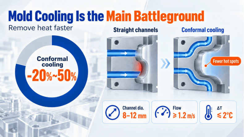
Conformal cooling channels follow the cavity geometry more closely and can improve heat removal in areas that conventional drilled channels cannot reach effectively. In suitable applications, cooling-time reductions of approximately 20%–50% may be possible, but this is a reference range rather than a guaranteed result. The benefit depends on the original cooling layout, part geometry, material, and the quality of the redesigned cooling circuit.
High-conductivity inserts, such as beryllium copper inserts where appropriate, can help remove heat from localized hot spots. Baffles and bubblers can improve cooling in deep cores where a conventional straight channel is insufficient. These options should be selected to solve a specific thermal problem rather than added indiscriminately to the mold.
Cooling-channel dimensions and coolant conditions also influence performance. For some thick-walled applications, channel diameters of around 8–12 mm, a channel-to-cavity distance of approximately 1–1.5 times the channel diameter, coolant velocity of at least 1.2 m/s, and an inlet-to-outlet temperature difference of around 2°C can serve as initial design references. Final values depend on material, channel length, mold geometry, circuit pressure drop, and cooling-unit capability. They should be validated for the actual tool rather than treated as universal specifications.
Cooling performance can also deteriorate over time. Scale or deposits inside water channels reduce heat-transfer efficiency, potentially increasing cycle time even when the part design and machine settings remain unchanged. If a previously stable process begins taking longer to reach the same part condition, inspect the cooling circuit and temperature-control system before assuming that the molding parameters need to be changed.
Process Settings: Melt Temperature, Packing, and Cooling
Once part geometry and mold cooling are under control, process settings can provide further opportunities to reduce cycle time. The objective is to identify unnecessary time or excess heat without moving the process outside its acceptable operating window. Temperature changes, packing adjustments, and cooling-time reductions should therefore be evaluated against the material requirements and the quality of the molded part.
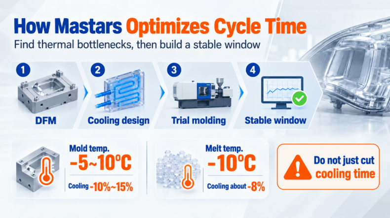
Mold temperature is one variable worth testing. Under suitable conditions, reducing mold temperature by 5–10°C may reduce cooling time by approximately 10%–15%. However, the effect depends on the resin and the required surface and dimensional performance. A lower mold temperature is not automatically better, especially for optical parts or materials sensitive to residual stress.
Melt temperature can also be reviewed. Where the material still fills the cavity reliably and plasticizing remains stable, reducing unnecessary melt temperature by around 10°C may shorten cooling time by approximately 8% in some conditions. These figures are starting points for controlled trials, not guaranteed outcomes. Excessive temperature reductions can affect flow, surface quality, or filling stability.
Packing time requires a different approach. Thick-walled parts need sufficient packing to compensate for shrinkage, but extending the packing stage beyond gate freeze generally provides little additional benefit because the cavity can no longer be fed effectively through the frozen gate. The key is to establish when additional packing stops meaningfully changing the part, rather than selecting an arbitrary shorter setting.
A controlled trial can help distinguish useful packing time from unnecessary delay:
- Record part weight and critical dimensions at several packing-time settings while holding other relevant variables constant.
- Look for the point at which additional packing produces little further change in part weight or dimensional behavior.
- Check for sink marks, voids, and other signs of inadequate packing before accepting a shorter setting.
- Repeat the test to confirm that the result is stable rather than a one-off improvement.
Part weight is a useful indicator of packing behavior, but it cannot establish quality by itself. Gate geometry, material behavior, and local shrinkage still matter. The final settings must satisfy the part's dimensional, appearance, and functional requirements.
Defect Diagnosis: What to Check When the Cycle Is Too Short
If defects appear after reducing cycle time, the next step is to identify which process change caused them. Different symptoms point to different possible causes, and adding cooling time indiscriminately may hide the symptom without resolving the underlying problem. Compare the affected features with the previous stable process and change one variable at a time where practical.
| Observed issue | What to investigate | Useful next step |
|---|---|---|
| Sink marks or internal voids | Local thick sections, packing adequacy, gate freeze, cooling conditions | Check packing behavior and whether the thick section is receiving sufficient support during shrinkage |
| Warpage or dimensional drift | Uneven cooling, residual stress, ejection temperature, geometry | Compare critical dimensions across repeated cycles and after the part has stabilized |
| Optical or surface defects | Mold temperature, cooling uniformity, material condition, residual stress | Inspect optical areas and review temperature changes against the required appearance and optical performance |
| Cycle time becomes inconsistent | Cooling-water flow, channel deposits, temperature-control stability, machine sequence | Check the cooling circuit and process records before making further parameter changes |
For example, if a shorter cooling time causes a thick boss to sink while surrounding dimensions remain stable, the issue may be concentrated in that section rather than across the entire part. Local cooling improvements or a design change may be more effective than increasing cooling time for every area. If dimensions vary between cycles, check whether mold temperature and cooling performance are consistent before concluding that the nominal cooling setting is too short.
For a broader review of common molding defects and their causes, see Mastars' guide to preventing injection molding defects before production.
Validate the Improvement Before Production
A shorter cycle is only an improvement if the part remains within specification over repeated cycles. A successful trial should demonstrate that the reduced cycle time is repeatable and that critical dimensions, appearance, assembly relationships, and functional requirements remain acceptable. For optical components, dimensional checks alone may not be sufficient; relevant optical requirements must also be verified.
A practical validation sequence is:
- Establish a baseline. Record the original cycle time, stage timings, process settings, part weight, critical dimensions, and relevant defect observations.
- Identify the limiting stage. Determine whether cooling, packing, screw recovery, mold movement, or ejection is restricting the cycle.
- Change one variable or a clearly defined group of related variables. Avoid changing several unrelated settings at once, because the effect of each change becomes difficult to isolate.
- Repeat the trial. Confirm that the shorter cycle produces consistent results across repeated shots rather than relying on the fastest individual cycle.
- Inspect the relevant features. Use dimensional inspection, CMM where appropriate, appearance checks, and optical testing when required by the application.
- Document the accepted process window. Record the settings and conditions that consistently produce acceptable parts so the improvement can be reproduced during production.
Dimensional measurements taken immediately after ejection may not tell the whole story. Where the material or application is sensitive to post-molding shrinkage or stress relaxation, compare measurements at a consistent time after molding and follow the applicable inspection requirements. This helps distinguish an apparently acceptable part at ejection from one that remains stable after cooling and conditioning.
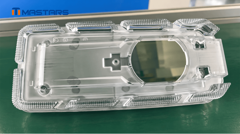
Transparent molded parts require careful control of cooling and dimensional stability.
Mastars' injection molding services support projects from tooling and process development through manufacturing. Reviewing the part geometry, material, critical dimensions, and production requirements together helps determine which cycle-time changes are technically viable before they are carried into production.
Choosing an Improvement That Pays Off
The best cycle-time reduction is the one that improves usable production output at an acceptable total cost. A tooling modification may deliver a larger time saving than a process adjustment, but it also introduces upfront engineering, manufacturing, and validation costs. Conversely, a small parameter change may be worthwhile if it produces repeatable savings without adding quality risk or requiring new tooling.
Before committing to a cooling redesign or structural change, compare the expected benefit with the actual production constraint:
- Cycle-time reduction: Estimate the improvement against the existing stable cycle, not an unusually slow or defective run.
- Annual production volume: A small saving per part can add up at high volumes, while expensive tooling changes may be harder to justify for limited quantities.
- Tooling and engineering costs: Include cooling-system modifications, inserts, design work, trials, and inspection.
- Quality and scrap risk: Consider whether the change creates new risks involving warpage, optical performance, dimensional stability, or repeatability.
- Machine utilization: Confirm that cycle time is actually limiting output. If production is constrained by material handling, downstream operations, or another machine, faster molding may not increase delivered output.
For example, conformal cooling may be attractive when a persistent hot spot limits a high-volume production run. For a low-volume project, improving a conventional cooling circuit or adjusting the part geometry may offer a better balance between cost and benefit. The decision should be based on the actual bottleneck, the expected production volume, and the evidence from trials.
If a thick-walled automotive lighting part has a long molding cycle, share the CAD model, material requirements, critical dimensions, and current cycle-time information where available. Include any known sink marks, warpage, optical requirements, or cooling-related concerns.
Mastars can review the part and manufacturing requirements to help identify potential design and tooling constraints, evaluate suitable cooling approaches, and determine what needs to be validated before production.
Get a Quote →Frequently Asked Questions
What determines injection molding cycle time?
Injection molding cycle time depends on filling, packing, cooling, screw recovery, mold movement, and ejection. For thick-walled components, cooling is often the dominant stage because heat must travel from the interior of the part to the mold before safe ejection. The actual bottleneck should be confirmed from cycle data rather than assumed from wall thickness alone.
How can I calculate injection molding cycle time?
Measure the elapsed time for a complete, repeatable molding cycle, from one cycle start to the next, using the same production conditions. Record the timings for filling, packing, cooling, screw recovery, mold opening and closing, and ejection where the machine data allows. Check whether any operations overlap before adding stage timings together, and use a stable production baseline for comparison.
How much can conformal cooling reduce injection molding cycle time?
In suitable applications, conformal cooling may reduce cooling time by approximately 20%–50%, but the result depends on the existing cooling layout, part geometry, material, and thermal bottleneck. The percentage should not be treated as a guaranteed reduction for every mold. A cooling redesign should be evaluated through mold analysis where appropriate and verified during molding trials.
Can I reduce cooling time without causing defects?
Yes, if the current process contains unnecessary cooling time or the mold can remove heat more effectively. Start by confirming the part's thermal and dimensional behavior, then reduce cooling time in controlled steps while checking for sink marks, voids, warpage, dimensional drift, and relevant appearance or optical defects. If the part becomes unstable, revisit the cooling design, local wall thickness, and process conditions rather than simply accepting the shorter timer.
What information should I provide for a cycle-time review?
A CAD model, resin grade, wall-thickness information, critical dimensions, target production volume, and current cycle time provide a useful starting point. If available, include the stage timings, mold temperature, melt temperature, packing and cooling settings, defect photos, and inspection results. You do not need to have every parameter ready to start the discussion; the initial information can help identify which details need further investigation.
Hot Articles
Hot Tags
Stay Connected!


Manufacturing on Demand
Please fill in the following information to obtain plan details (information is confidential and not disclosed publicly), we will contact you within 24 hours, please keep your phone available!
Upload a 3D/2D model to see instant pricing, lead time, and DFM feedback.