



3D Printing and CNC Machining: A Cost, Precision, and Process-Selection Guide


A new drawing lands in your inbox in the middle of an NPI sprint. Send it to the 3D printer down the hall, or queue it up on the CNC mill? It looks like a small decision. It isn't. That single call ripples through your prototyping budget, your iteration speed, and the mechanical properties of the part that eventually ships. Get it wrong twice in a row and a "quick prototype" quietly turns into a two-week detour.
Quick answer: 3D printing (additive manufacturing) is cheaper and faster for one-off or low-volume parts and handles complex internal geometry with zero tooling cost. CNC machining (subtractive manufacturing) holds tighter tolerances — down to roughly ±0.005 mm on critical features — preserves full material strength, and gets cheaper per part as volume climbs past somewhere between the tens and low hundreds of units. Most hardware teams use both: 3D printing to iterate fast early on, CNC machining for functional and production parts, and sometimes a hybrid print-then-machine workflow to get both in a single component.
This guide skips the textbook definitions and goes straight to the numbers engineers actually need: where the cost curves of 3D printing and CNC machining cross, what tolerances and surface finishes each process can realistically hold, which materials survive FDA or AS9100 scrutiny, and how a hybrid workflow can give you the best of both. By the end, you should be able to look at a part file and know, without guessing, which process — or combination of processes — belongs on the routing sheet.
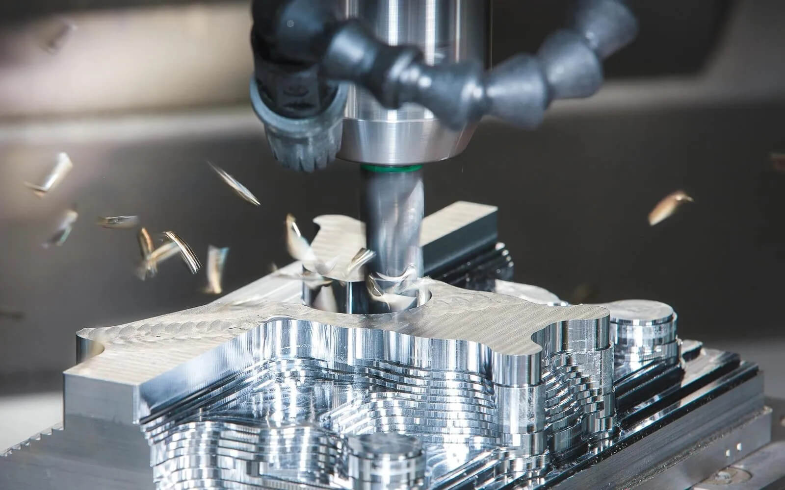
3D Printing vs CNC Machining Cost: Where the Break-Even Point Is
The two processes solve the same problem — turning a CAD model into a physical part — from opposite directions. 3D printing builds a part layer by layer from a digital file, with no tooling and almost no constraint on internal geometry. CNC machining starts with a solid block of material and removes everything that isn't the part, guided by a cutting tool that has to physically reach every surface. That single difference — build up vs. cut away — is the root of nearly every cost and design tradeoff between them.
The Cost Curve, and Where It Bends
For a single prototype or a run of ten pieces, 3D printing almost always wins on price. There's no programming, no fixturing, no tooling — the machine reads the file and starts building. CNC, by contrast, carries fixed costs that show up on the very first part: someone has to write the toolpath, simulate it, set up work-holding, and touch off the tool. On a one-off, those fixed costs dominate the quote.
As volume climbs, the picture flips. Setup and programming costs get amortized across more parts, and the marginal cost of an additional CNC part — mostly spindle time and material — starts to look a lot more competitive. Depending on part complexity and size, the crossover typically lands somewhere between the tens and low hundreds of units. Beyond that point, CNC's per-unit economics usually beat 3D printing, especially once you factor in that machined parts rarely need the extensive post-processing that printed parts do.
What's Actually in a CNC Machining Quote
A CNC price isn't just "machine time." It's a stack of three cost centers:
Machine time — the minutes the spindle is actually cutting, driven by material removal rate and part complexity.
Setup and fixturing — programming, work-holding design, and the first-article calibration that has to happen before production cutting starts.
Post-processing — deburring, cleaning, and any secondary finishing before the part ships.
On a low-volume order, setup and fixturing can easily outweigh the actual cutting time. That's precisely why small CNC batches feel disproportionately expensive compared to 3D printing — you're paying for the setup once, on a very small number of parts to spread it across.
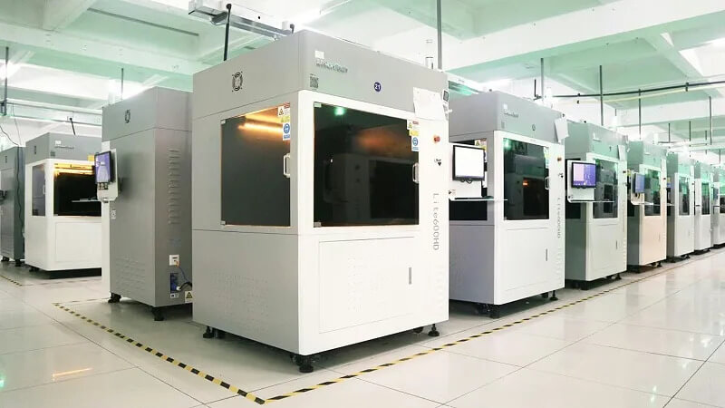
A Feature-Based Decision Tree: 3D Printing vs CNC Machining
Rather than starting from cost alone, look at the part's geometry first:
Thin walls, honeycomb or lattice infill, fully enclosed internal cavities → these defeat a cutting tool that needs a straight-line path to every surface. 3D printing wins by default.
Standard prismatic or rotationally symmetric geometry, tight-tolerance mating features, load-bearing structure → CNC's solid, isotropic stock and tighter tolerance band make it the safer choice.
The anatomical heart model discussed later in this guide is a good illustration of the first case: open cavities, thin edges, and internal channels that would have demanded an expensive, high-risk fixturing plan on a CNC machine went through SLA printing with zero tooling investment instead.
One practical note for anyone sourcing small-batch CNC work during a prototyping phase: setup and fixturing costs hit hardest exactly when order quantities are lowest, so it's worth confirming your manufacturing partner doesn't penalize you for ordering five or ten pieces. Mastars' rapid prototyping service is built around that reality — no minimum order quantity, so a single test part costs what it should, not what a batch-oriented pricing model says it should.
3D Printing and CNC Machining Materials: Choosing the Right One
Material selection isn't just about which resin or alloy looks good on a spec sheet — it's about how that material behaves once it goes through a specific process.
Polymers: PLA, ABS, ASA, PETG, and PEEK
PLA is the default FDM material for concept models — cheap and easy to print, but too brittle and heat-sensitive for functional use. ABS and its UV-stable cousin ASA hold up better mechanically and outdoors, respectively. PETG splits the difference with good impact and chemical resistance. PEEK sits at the top of the polymer stack: chemically inert, dimensionally stable, and rated for repeated sterilization, which is why it shows up in both CNC-machined and printed spinal implants and imaging components.
The catch with printed polymers is anisotropy. An FDM part is only as strong as the bond between its layers, and that bond is almost always weaker than the material itself — so a printed bracket can fail along its Z-axis under a load it would easily survive if oriented differently. SLS and MJF parts, built from sintered powder, come closer to isotropic behavior but still don't fully match a machined part. A CNC-machined polymer part, cut from solid extruded or cast stock, keeps the material's native isotropic and thermal properties intact — no layer lines, no weak axis.
Metals: Aluminum 6061, 17-4PH Stainless, and Titanium
6061 aluminum is the workhorse: good strength-to-weight, easy to cut, and it takes anodizing well, which is why it dominates consumer electronics housings and structural brackets. Precipitation-hardening stainless steels like 17-4PH step up strength and corrosion resistance for tooling and medical components. Titanium alloys (Ti-6Al-4V) deliver the best strength-to-weight ratio and excellent biocompatibility, but they're notoriously hard to machine — low thermal conductivity and high elastic recovery cause tool wear and springback, which is exactly why metal 3D printing (SLM/DMLS) has carved out a niche for titanium parts with complex internal geometry that would otherwise require extensive multi-axis setup.
DFM Constraints to Check Before You Quote
CNC design rules include minimum wall thickness, maximum depth-to-diameter ratios for pockets, and tool-access strategy — anything a straight or angled cutter can't physically reach needs a redesign, a different fixture, or a different process. 3D printing has its own limits: minimum feature size, maximum overhang angle before support structures are required, and whether those supports can actually be removed from an enclosed cavity once printing is done.
Compliance: FDA, AS9100, ISO 13485, and IATF 16949
SLA and DLP resins can capture extremely fine surface detail, but many photopolymers are too brittle to survive the clamping forces of a secondary CNC operation — worth checking material-specific machinability notes before combining the two processes on one part. On the regulatory side, medical devices generally need materials with ISO 10993 biocompatibility data and a quality system built on ISO 13485, while aerospace parts often require AS9100-audited suppliers and full material traceability. Mastars' medical manufacturing program is built around ISO 13485-aligned processes and cleanroom assembly, and its automotive work runs under IATF 16949 — worth checking with any manufacturing partner before a regulated part ever reaches the shop floor. Material pairing matters here too: the PEEK-PTFE valve body covered further down was specified as that particular combination precisely because both polymers meet the chemical-inertness and dimensional-stability bar semiconductor fluid handling demands, and the finished part had to be cleanroom-ready with no secondary bonding step.
Case Study: Breaking Through Complex Geometry with 3D Printing
A medical-training customer needed an anatomically accurate heart model — open cavities, thin edges, internal channels, and layered anatomical detail that would be brutal to fixture and cut conventionally. Mastars built it via SLA 3D printing in ABS resin, which meant zero tooling investment despite the geometric complexity. Printing was only step one: the parts went through two rounds of hand sanding and two coating passes (primer, then final paint) to get a presentable surface, then three separate inspections — surface quality, critical dimensions, and a pull test rated to 10 kg — before anything qualified for packing and shipment. Parts that didn't pass were rejected outright. It's a useful reminder that "printable" and "deliverable" aren't the same thing: the process route has to plan for post-processing and inspection from day one, not treat them as an afterthought once the print finishes. Read the full case study →

CNC Machining vs 3D Printing Accuracy: Tolerances and Surface Finish
This is where "3D printing vs. CNC machining" stops being theoretical and starts being a spec sheet conversation.
Typical Tolerances: 3D Printing vs CNC Machining
As a general guide, FDM parts typically hold tolerances in the range of ±0.2–0.5 mm, SLA/DLP can tighten that to roughly ±0.05–0.1 mm on small parts thanks to fine layer resolution, and SLS/MJF land somewhere in between depending on part size and orientation. CNC milling and turning are in a different league: ±0.01–0.05 mm is routine on a well-programmed job, and tightly controlled setups with closed-loop servo control can hold tolerances down to roughly ±0.005 mm on critical features — the kind of precision that matters when a part has to mate with something else without a shim.
Post-Processing and Surface Finish Options
Printed parts typically need support removal and sanding before they look presentable, and even then the surface texture carries some evidence of the layer-by-layer build. CNC parts come off the machine with a consistent, controllable surface finish and are fully compatible with industrial finishing: bead/sand blasting, Type II or Type III anodizing on aluminum, electroplating, PVD coating, or passivation on stainless steel. Each of those adds lead time and cost, so it's worth specifying the finish requirement up front rather than discovering mid-project that a part needs anodizing it wasn't quoted for.
Verifying Tolerances: GD&T, CMM, and FAI Reports
In real supply chains, tolerance claims mean nothing without inspection data behind them. A proper first-article inspection (FAI) report should include a full dimensional report against the drawing (typically via CMM or optical scanning for freeform surfaces), material certification, and — for regulated industries — process capability data (Cpk) showing the process stays in tolerance across a production run, not just on the first part measured.
Case Study: CNC's Edge in High-Precision Functional Parts
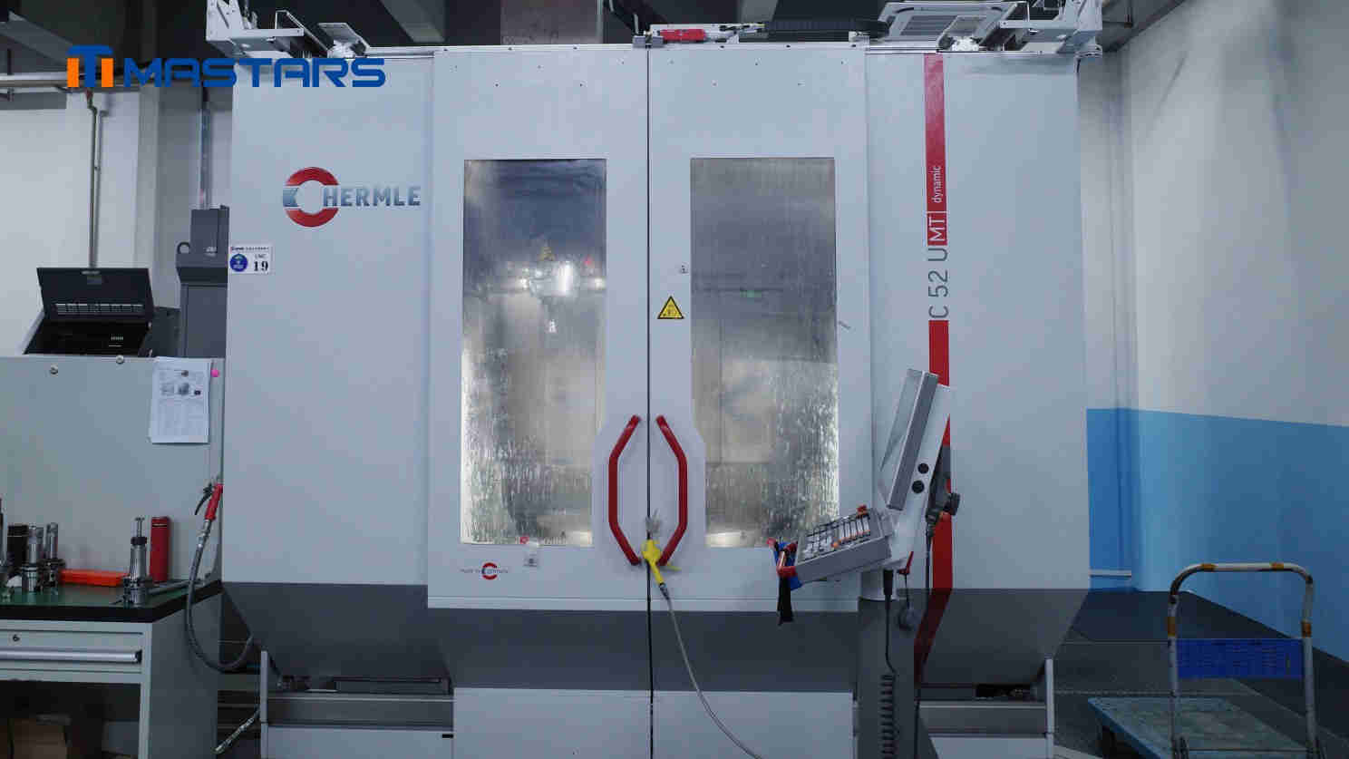
A semiconductor customer in Australia needed a valve body that paired a rigid PEEK outer shell with a soft PTFE inner liner — chemically inert, dimensionally stable, and ready for cleanroom assembly with no secondary bonding. Machining two dissimilar plastics in one part is unforgiving: the wrong tooling smears PTFE across the PEEK surface, and PEEK's heat sensitivity means spindle speed and cooling have to be tuned per material. Mastars machined the entire part — external threads, internal PTFE bore, flange mounting holes — in a single clamping on a Hermle 5-axis machining center, holding concentricity between the outer threads and inner bore to 0.02–0.03 mm and cutting handling and alignment steps by roughly 40–50% versus a multi-setup approach. Read the full case study →
The same one-piece logic showed up on a European aerospace-related structural part: rather than splitting a ribbed, thin-walled aluminum housing into several machined pieces and assembling them afterward — which stacks tolerance error at every joint — Mastars five-axis machined it as a single structure, cutting the estimated assembly-error risk by roughly 30–40% and shortening prototype confirmation time by about 20–30%. Both cases make the same point: once a part has to hold GD&T callouts under real assembly or process conditions, precision isn't just about the machine's rated accuracy — it's about how few times the part gets re-fixtured between the first cut and final inspection.
Combining 3D Printing and CNC Machining: Hybrid Workflows and Sourcing
The most experienced NPI teams don't treat this as an either/or decision — they combine both processes on a single part.
A Practical Hybrid Workflow: Print Then Machine
3D print a near-net-shape blank — this is especially useful with metal SLM, where the printer can generate a complex internal structure or organic form that would be nearly impossible to machine from solid stock — then leave extra material on the critical mating surfaces. CNC finishing then takes those specific features to final tolerance. On the design side, that means partitioning the model early: flag which zones stay "as printed" and which need machining stock, and add alignment tabs or datum features so the part can be located accurately in a fixture after printing. On the CAM side, the printed blank has to be registered to program zero, usually via a structured-light scan or CMM probing routine, before any cutting starts.
Sourcing Strategy: Keep Both Processes Under One Roof
For low-volume runs, the decision often comes down to whether to keep production local or use an overseas manufacturing partner with broader process coverage — the right call depends on lead time pressure, part complexity, and how much hands-on iteration the design still needs.
The same principle showed up within a single process on the aerospace-related structural part discussed earlier: it got more accurate, not less, when Mastars kept it as one five-axis machining route instead of splitting it into several pieces and assembling them afterward — fewer handoffs meant fewer places for error to creep in. That logic scales up to sourcing decisions, too.
One sourcing mistake shows up often enough to call out directly: splitting the 3D-printed blank and the CNC finishing operation across two different suppliers. It seems logical on paper — each vendor does what they're best at — but in practice it invites tolerance stack-up between the two processes and makes it much harder to pin down responsibility when a part comes back out of spec. A single manufacturing partner that runs both processes in-house, with one engineering team accountable for the whole part rather than just their half of it, removes that failure mode entirely. Mastars' CNC machining services sit under the same roof as its additive manufacturing capability, backed by an in-house design and engineering team that can carry a hybrid part from DFM review through final inspection without handing it off between vendors.
Get a Free DFM Review and Instant Quote
Reading about tolerances and cost curves only gets you so far. The fastest way to know whether your part belongs on a 3D printer, a CNC mill, or both is to have someone look at the actual drawing.
Upload your 3D CAD file for a free DFM review and process recommendation from a manufacturing engineer — no theoretical advice, just a specific answer for your part. Whether you need a same-week 3D-printed prototype or a few hundred CMM-inspected CNC parts for a pilot run, Mastars quotes fast and works with no minimum order quantity, so you're not penalized for testing before you commit to volume.
Upload Your Drawing for an Instant Quote & DFM Review →
FAQ: 3D Printing and CNC Machining
What are the main tradeoffs between 3D printing and CNC machining for prototyping versus production?
3D printing wins on setup cost and design freedom, making it ideal for early-stage prototypes and complex internal geometry. CNC machining wins on tolerance, surface finish, and material properties, making it better for functional testing and production parts. Most programs use 3D printing early and shift to CNC as designs stabilize and volumes grow.
How do cost and lead time compare between additive and subtractive manufacturing across different batch sizes?
At single-digit quantities, 3D printing is typically cheaper and faster because it skips tooling and setup entirely. As batch size grows into the hundreds, CNC's per-unit cost drops as fixed setup costs get spread across more parts, often overtaking 3D printing on total program cost.
Which materials are best suited to 3D printing and which are better for CNC machining, and what limits should I watch for?
3D printing suits polymers like PLA, ABS, and SLS nylon plus a growing range of metal powders for complex geometry. CNC machining works with nearly any engineering plastic or metal stock and preserves the material's native, isotropic properties. Watch for print-induced anisotropy and machining-related tool access limits on deep or undercut features.
What tolerances and surface finishes can I realistically expect from common 3D printing and CNC processes?
FDM typically holds around ±0.2–0.5 mm, SLA/DLP can reach ±0.05–0.1 mm, and SLS/MJF fall in between. CNC milling and turning routinely hold ±0.01–0.05 mm, with tightly controlled setups reaching roughly ±0.005 mm. CNC also supports a much wider range of industrial surface finishes, including anodizing, plating, and PVD coating.
How does a hybrid additive-then-subtractive workflow work in practice, and when is it worth the extra effort?
A hybrid workflow 3D-prints a near-net-shape blank — often for complex internal geometry — then CNC-finishes the critical mating surfaces to final tolerance. It's worth the added design and CAM complexity when a part needs both geometric freedom and tight tolerance on specific features, which neither process alone can deliver as efficiently.
Should I buy equipment or use a service bureau for small-batch production, and how do I evaluate providers?
For most small-batch runs, an outside manufacturing partner is more cost-effective than buying and maintaining equipment in-house. Evaluate providers on process breadth (ideally both 3D printing and CNC under one roof), inspection capability (CMM, material certs), relevant quality certifications, and whether they impose a minimum order quantity that penalizes low-volume testing.
Hot Articles
Hot Tags
Stay Connected!


Manufacturing on Demand
Please fill in the following information to obtain plan details (information is confidential and not disclosed publicly), we will contact you within 24 hours, please keep your phone available!
Upload a 3D/2D model to see instant pricing, lead time, and DFM feedback.